
Optical gyroscope system based on silicon nitride waveguide resonant cavity

An optical gyroscope and resonant cavity technology, applied in the field of optical gyroscopes, can solve the problems of increased system cost, large polarization noise, large loss of waveguide resonator cavity, etc., and achieve the effect of eliminating transfer function differences, reducing polarization noise, and improving polarization performance.

Active Publication Date: 2021-08-27
BEIHANG UNIV
View PDF15 Cites 1 Cited by
  • Summary
  • Abstract
  • Description
  • Claims
  • Application Information

AI Technical Summary

Problems solved by technology

The traditional integrated optical gyroscope generally uses a silica waveguide cavity. The silica waveguide resonator has a large loss, a low quality factor, and it is difficult to achieve polarization performance, which will introduce a large polarization noise into the system and require an auxiliary polarization controller. This will undoubtedly increase the volume and cost of the system, affecting the application and promotion of integrated optical gyroscopes
[0004] In summary, for the existing silicon dioxide-based resonant integrated optical gyroscope system, due to the large loss of the silicon dioxide waveguide resonator cavity, the quality factor is low , and it is difficult to achieve polarization performance, resulting in large polarization noise in the system, requiring an auxiliary polarization controller, which undoubtedly increases the system cost

Method used


Image

  • Optical gyroscope system based on silicon nitride waveguide resonant cavity

Examples


Embodiment Construction

[0024] The following will clearly and completely describe the technical solutions in the embodiments of the present invention with reference to the accompanying drawings in the embodiments of the present invention. Obviously, the described embodiments are only some, not all, embodiments of the present invention. Based on the embodiments of the present invention, all other embodiments obtained by persons of ordinary skill in the art without making creative efforts belong to the protection scope of the present invention.

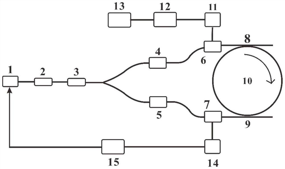
[0025] The object of the present invention is to provide an optical gyro system based on a silicon nitride waveguide resonant cavity, so as to improve the polarization performance of the optical gyro system and reduce the system cost.

[0026] In order to make the above objects, features and advantages of the present invention more comprehensible, the present invention will be further described in detail below in conjunction with the accompanying drawings and s...


PUM


Abstract

The invention relates to an optical gyroscope system. A light source is connected with the input end of a straight waveguide modulator; the output end of the straight waveguide modulator is connected with the input end of a Y waveguide phase modulator; the output end of the upper modulation arm of the Y waveguide phase modulator is connected with the input end of a first optical circulator; the output end of the lower modulation arm of the Y waveguide phase modulator is connected with the input end of a second optical circulator; the Y waveguide phase modulator is used for splitting the modulated optical signal; the output end of the first optical circulator is connected with the first waveguide coupler; the output end of the second optical circulator is connected with the second waveguide coupler; the reflecting end of the first optical circulator is connected with the signal receiving module; the reflection end of the second optical circulator is connected with the frequency locking module; the frequency locking module is also connected with the light source; and the first waveguide coupler and the second waveguide coupler are also connected with the resonant cavity. The polarization performance of the optical gyroscope system can be improved, and the system cost can be reduced.

Description

technical field [0001] The invention relates to the technical field of optical gyroscopes, in particular to an optical gyroscope system based on a silicon nitride waveguide resonant cavity. Background technique [0002] Inertial technology is the only core technology with the ability to acquire fully autonomous real-time motion information. It has the advantages of high reliability and strong anti-interference ability, and plays an irreplaceable key role in many fields of national defense security and national economy and people's livelihood. With the development of inertial technology and the gradual expansion of the application range, in order to realize the accurate attitude detection of moving carriers, higher requirements are put forward for inertial devices, among which the high reliability, miniaturization and low The need for cost is particularly urgent. As the second generation optical gyroscope, the integrated optical gyroscope is different from traditional mechan...

Claims


Application Information

Patent Timeline
Patent Type & Authority Applications(China)
IPC IPC(8): G01C19/72
CPCG01C19/721
Inventor 冯丽爽冯昌坤刘丹妮李慧青晨
Owner BEIHANG UNIV
Learn More