Method and device for realizing motor control based on FPGA

A motor control and computer program technology, applied in the field of signal processing, can solve the problems of medium separation or multiple separation, excessive friction between the separation components and the medium, and inability to achieve precise control.

Pending Publication Date: 2021-08-20
SHENZHEN YIHUA COMP +2
View PDF10 Cites 0 Cited by
  • Summary
  • Abstract
  • Description
  • Claims
  • Application Information

AI Technical Summary

Problems solved by technology

[0003] However, during the separation process of the medium, although the rotational speed of the motor is fixed, due to factors such as the newness and contamination of the medium, the quality, thickness, and space occupied are different, the relative position between the separation component and the medium is prone to change, resulting in The friction between the separation component and the medium is too large or too small, the medium and the separation element are either loose or tight, and the separation of the medium is not carried out at a uniform speed, resulting in the phenomenon of medium separation or multiple separation.
As a result, the separation quality cannot be effectively guaranteed
The changes in these parameters such as distance and friction are very small, but they have a great impact on the separation effect of the medium, and the traditional control method cannot achieve accurate real-time adjustment. If it is not processed and corrected in time, it will even cause serious damage to the medium. and device consequences
At present, the traditional processing method is to control the motor to drive the separation component to separate the medium through ARM, MCU, etc. The traditional control method can only solve the obvious separation problem, and its real-time and accuracy cannot solve the separation problem caused by subtle parameter changes. Achieve precise control and precise separation

Method used


Image

  • Method and device for realizing motor control based on FPGA
  • Method and device for realizing motor control based on FPGA
  • Method and device for realizing motor control based on FPGA

Examples


Embodiment Construction

[0062] In order to make the above objects, features and advantages of the present invention more comprehensible, the present invention will be further described in detail below in conjunction with the accompanying drawings and specific embodiments.

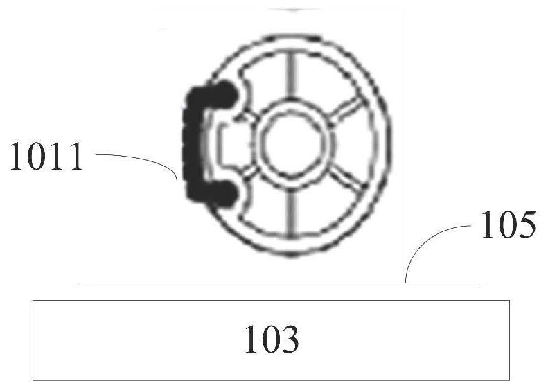
[0063] refer to figure 1 , shows a schematic structural view of media separation inside a container of the present invention, including a separation assembly 101, a detection assembly 102, a medium carrying assembly 103 and a motor 104; wherein, the separation assembly 101 is provided with a separation element 1011.

[0064] Wherein, the detection component 102 is used to judge the contact state between the medium and the separation element 1011. In one example, the detection component 102 can be an infrared sensor, and the infrared sensor emits infrared rays to the surface of the medium to judge the medium and the separation element 1011 according to the return of the infrared rays. The contact state of the separation element 101...


PUM


Abstract

An embodiment of the invention provides a method and a device for realizing motor control based on an FPGA. The method comprises the steps of: acquiring the first phase information of a preset separation assembly when a preset medium separation instruction is received; determining a detection time point for detecting the preset detection component according to the first phase information; detecting the detection assembly at the detection time point to obtain a detection result; and according to the detection result, adopting a motor to control the preset medium bearing assembly to move towards the separation assembly. According to the method and the device of the invention, the positions of the medium bearing assembly and the separation assembly are monitored in real time, and the medium bearing assembly is synchronously moved in real time according to the monitoring result, so that the moving time point of the medium bearing assembly can be accurately controlled, and the medium cannot be in contact with the separation element in the moving process to cause the stress change of the medium and influence the separation of the medium.

Description

technical field [0001] The invention relates to the technical field of signal processing, in particular to a method for realizing motor control based on FPGA and a device for realizing motor control based on FPGA. Background technique [0002] The container used to store the medium often involves the problem of how to separate the medium in the container. The separation of the medium in the existing container is often achieved by separating the medium from the container through the friction between the separation component in the container and the medium. technical effect. [0003] However, during the separation process of the medium, although the rotational speed of the motor is fixed, the relative position between the separation component and the medium is likely to change due to factors such as the newness and contamination of the medium, the quality, thickness, and space occupied, resulting in The friction between the separation component and the medium is too large or ...

Claims


Application Information

Patent Timeline
IPC IPC(8): G07D11/18G07D11/12
CPCG07D11/18G07D11/0096
Inventor 刘华朱忆军
Owner SHENZHEN YIHUA COMP
Why Eureka
Try Eureka