Vertical anaerobic process tank integrated triphase separator

An anaerobic treatment, three-phase separator technology, applied in the field of vertical anaerobic treatment tank integrated three-phase separation device, can solve the problems of loss of anaerobic bacteria, turbidity of effluent, poor resistance to shock load, etc., and achieves convenient operation. , The effect of low infrastructure cost and small footprint

Active Publication Date: 2011-05-18
SHANGHAI TIANFENG ENVIRONMENTAL PROTECTION
View PDF0 Cites 0 Cited by
  • Summary
  • Abstract
  • Description
  • Claims
  • Application Information

AI Technical Summary

Problems solved by technology

The disadvantages of the above-mentioned device are: ①The gas in the gas, sludge and water mixture will enter the sedimentation area, that is, before the sludge and water enter the sedimentation area, the gas is not effectively separated and removed, and the leakage of gas into the sedimentation area interferes The separation effect of sludge and water makes the effluent turbid, the content of suspended solids is high, and anaerobic bacteria are also lost; There is also falling sludge, and the two form convection, which affects the separation effect of the sludge and causes turbidity in the effluent, which is not conducive to the operation of subsequent units; Adjusted to maintain a certain sludge concentration and a longer sludge age in the anaerobic treatment tank, and the ability to resist shock loads is poor

Method used


Image

  • Vertical anaerobic process tank integrated triphase separator
  • Vertical anaerobic process tank integrated triphase separator
  • Vertical anaerobic process tank integrated triphase separator

Examples


Embodiment

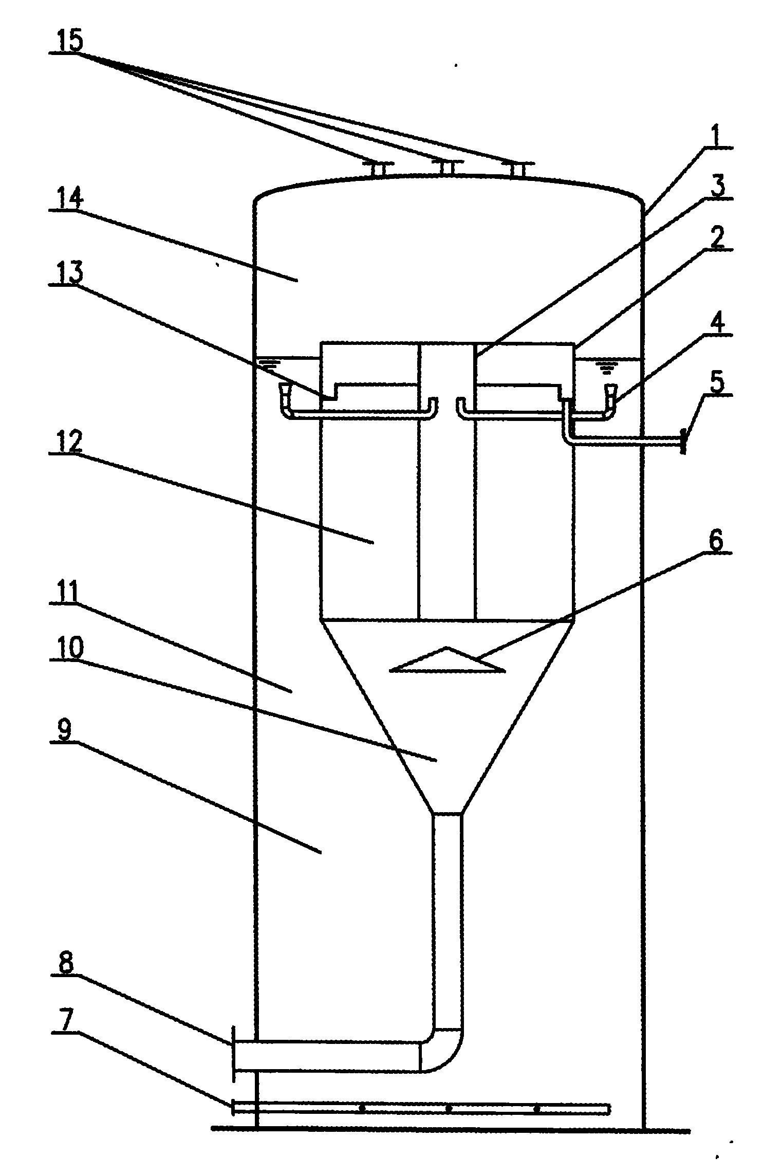
[0020] Such as figure 2 Shown is a schematic diagram of a vertical anaerobic treatment tank integrated three-phase separator, the vertical anaerobic treatment tank integrated three-phase separator consists of a vertical anaerobic tank 1, a sedimentation tank 2, a vertical enhanced gas-liquid Separation device 3, diversion pipe 4, outlet pipe 5, reflection plate 6, water inlet pipe 7, mud discharge pipe 8, reaction zone 9, mud bucket 10, gas-liquid separation zone 11, sedimentation zone 12, water collection tank 13, gas collection Chamber 14 and exhaust port 15.

[0021] The top of the vertical anaerobic tank 1 is provided with an exhaust port 15, the upper side of the vertical anaerobic tank 1 is provided with a gas collection chamber 14 with a height of 1.2 to 1.5 m, and the bottom of the vertical anaerobic tank 1 is provided with an inlet. Water pipe 7, sedimentation tank 2 is provided in the lower middle part of gas collection chamber 14, and a sump 13 is provided in the ...


PUM

PropertyMeasurementUnit
angleaaaaaaaaaa

Abstract

The invention provides a vertical anaerobic process tank integrated triphase separator, comprising a vertical anaerobic tank; the top of the vertical anaerobic tank is provided with an air outlet, the upper part of the vertical anaerobic tank is internally provided with a gas collection chamber, the bottom part of the vertical anaerobic tank is provided with a water inlet tube; the invention is characterized in that the middle part of the lower part of the gas collection chamber is provided with a sedimentation tank, the upper part of the sedimentation tank is internally provided with a watercollection tank, the bottom of the water collection tank is connected with a water outlet tube, the bottom of the sedimentation tank is connected with a mud bucket, the bottom of the mud bucket is connected with a dredge pipe, the middle part of the sedimentation tank is provided with a vertical reinforced gas-liquid separator, one end of the vertical reinforced gas-liquid separator is connected with the gas collection chamber and the other end is connected with the mud bucket; one end of a air chamber tube assy is arranged in the vertical gas-liquid separator, and the other end is arranged between the external side wall of the sedimentation tank and the internal side wall of the vertical anaerobic tank. The invention has the advantages of good separation effect, simple device and convenient operation.

Description

technical field [0001] The invention relates to a vertical anaerobic treatment tank integrated three-phase separation device, which belongs to the technical field of sewage treatment. Background technique [0002] CH is produced during anaerobic biological treatment 4 , CO 2 , NH 3 And other gaseous substances, the tiny bubbles formed by them will attach a large number of anaerobic bacteria clusters and rise with the water flow. How to control the loss of anaerobic bacteria mass, the design of gas-solid-liquid three-phase separator becomes the key. The effect of three-phase separation is good or bad, which directly affects the effect of anaerobic treatment. At present, there are various structural forms of three-phase separators: there are three-phase separators assembled on the construction site; there are three-phase separator modules that are produced in the factory and are more convenient for construction and installation. However, their structure and the body of th...

Claims


Application Information

Patent Timeline
Patent Type & Authority Patents(China)
IPC IPC(8): C02F3/28
Inventor 杨剑平徐耀林
Owner SHANGHAI TIANFENG ENVIRONMENTAL PROTECTION
Why Eureka
Try Eureka