
Surface-mounted component electroplating device

A technology for electroplating devices and chip components, which is applied in the direction of electrical components, electrical components, printed circuits, etc., can solve problems such as low efficiency of barrel plating, difficulty in circulation of electroplating solution, and reduced coating quality, so as to achieve good coating quality and improve electroplating efficiency Effect

Pending Publication Date: 2021-08-17
GUANGDONG FENGHUA ADVANCED TECH HLDG
View PDF0 Cites 0 Cited by
  • Summary
  • Abstract
  • Description
  • Claims
  • Application Information

AI Technical Summary

Problems solved by technology

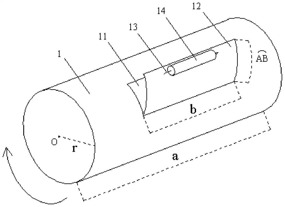
[0003] The purpose of the present invention is to overcome the deficiencies of the prior art, and provide a patch component electroplating device, which can solve the technical problem: in the prior art, due to the small size of the patch and the small holes on the drum, the circulation of the electroplating solution is difficult, and the electroplating The concentration of metal ions in the solution cannot be kept stable, which reduces the quality of the coating and the efficiency of barrel plating is low

Method used


Image

  • Surface-mounted component electroplating device
  • Surface-mounted component electroplating device
  • Surface-mounted component electroplating device

Examples


Embodiment Construction

[0035] The specific implementation manners of the present invention will be further described in detail below in conjunction with the accompanying drawings and embodiments. The following examples are used to illustrate the present invention, but are not intended to limit the scope of the present invention.

[0036] In the description of the present invention, it should be understood that the orientation or positional relationship indicated by the terms "upper", "lower", "left", "right", "top", "bottom" etc. Orientation or positional relationship is only for the convenience of describing the present invention and simplifying the description, and does not indicate or imply that the referred device or element must have a specific orientation, be constructed and operated in a specific orientation, and thus should not be construed as a limitation of the present invention. It should be understood that the terms "first", "second", etc. are used in the present invention to describe va...


PUM


Abstract

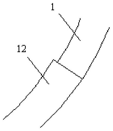
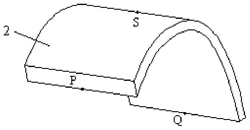
The invention discloses a surface-mounted component electroplating device which comprises an electroplating bath and a roller rotationally arranged in the electroplating bath. The rotating axis of the roller horizontally extends, an opening is formed in the roller, and a cover plate is rotationally arranged on the opening; a reset piece used for enabling the cover plate to keep sealing the opening is arranged on the cover plate, a rolling shaft is arranged on the outer side surface, away from the rotating axis of the cover plate, of the cover plate, and the rotating axis of the rolling shaft and the rotating axis of the cover plate are both parallel to the rotating axis of the roller. The curved-surface-shaped magnetic parts are further fixedly arranged in the electroplating bath, extend to the upper right direction of the roller from the upper left direction of the roller in an arc shape and are arranged at the outer side of the roller at intervals. According to the surface-mounted component electroplating device, barrel plating of small-size surface-mounted components can be stably carried out, good plating quality is obtained, and the electroplating efficiency is improved.

Description

technical field [0001] The invention relates to the field of electroplating, in particular to an electroplating device for chip components. Background technique [0002] The multi-functional requirements of electronic equipment require the small size of SMD components. For example, SMD components with a length of 0.6mm and a width of 0.3mm have been widely used in the prior art, and further applications of SMD components with a length of 0.4mm and a width of 0.2mm are becoming popular , and smaller patches such as 0.25mm in length and 0.125mm in width are also being developed. In order to meet the solderability and solder resistance requirements of surface mount components, in the manufacturing process of SMD components, after the terminal electrodes are formed, it is generally necessary to form a nickel layer and a tin layer on the terminal electrodes by barrel plating, that is, barrel electroplating. . For small-sized patch components as mentioned above, the size of the ...

Claims


Application Information

Patent Timeline
Patent Type & Authority Applications(China)
IPC IPC(8): H05K3/24H05K13/04
CPCH05K3/241H05K13/04
Inventor 陆亨麦雪清刘婕妤卓金丽何彦颖
Owner GUANGDONG FENGHUA ADVANCED TECH HLDG
Learn More