
Fly ash collecting device for hazardous waste incineration disposal

A technology for hazardous waste and collection devices, which is applied in the fields of combination devices, dispersed particle separation, chemical instruments and methods, etc., can solve the problems of different sizes of fine solid particles, pretreatment of fine solid particles, affecting the effect of fly ash collection, etc. The effect of better collection, easy subsequent use and processing, and strong practicability

Pending Publication Date: 2021-08-17
SHENYANG ACAD OF ENVIRONMENTAL SCI
View PDF0 Cites 0 Cited by
  • Summary
  • Abstract
  • Description
  • Claims
  • Application Information

AI Technical Summary

Problems solved by technology

[0002] With the development of industry, the amount of hazardous waste discharged during industrial production is increasing. Incineration is the main way to deal with hazardous waste. After incineration, the fine solid particles floating in the flue gas are called fly ash. If the fly ash is not properly collected, it will It will pollute the atmosphere and cause harm to organisms and humans, and the size of the fine solid particles is different. If it is not treated, it will affect the collection effect of fly ash
However, the existing fly ash disposal device does not pretreat the fine solid particles in the fly ash after incineration, the structure is complex and the collection effect is not good.

Method used


Image

  • Fly ash collecting device for hazardous waste incineration disposal
  • Fly ash collecting device for hazardous waste incineration disposal
  • Fly ash collecting device for hazardous waste incineration disposal

Examples


Embodiment Construction

[0021] The technical solutions of the present invention will be further described below through specific embodiments and in conjunction with the accompanying drawings.

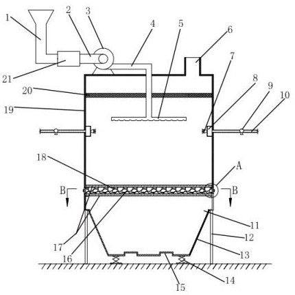
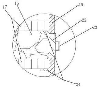
[0022] Such as Figure 1-Figure 3 As shown, the hazardous waste incineration disposal fly ash collection device includes a device housing 19 whose bottom end is fixed on the ground through support legs 12, and the upper surface of the device housing 19 is respectively provided with an air inlet and an exhaust port. The exhaust port is connected with an exhaust pipe 6 , and a fly ash outlet 11 is opened on the lower surface of the device housing 19 .

[0023] Wherein, a blower 3 is fixed above the device housing 19, and the inlet of the blower 3 is connected with a feeding pipe 2, and the inlet of the feeding pipe 2 is connected with the outlet of the turbine pulverizer 21, and the turbine pulverizer The feed inlet of machine 21 is connected with air inlet pipe 1, and the outlet of described blower 3 is connec...


PUM


Abstract

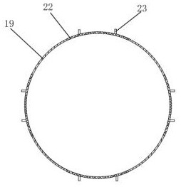
The invention relates to a fly ash collecting device, in particular to a fly ash collecting device for hazardous waste incineration disposal. The device comprises supporting legs, a device shell, an air inlet, an exhaust port, an exhaust pipe and a fly ash outlet, and is technically characterized in that an air blower is fixed to the upper portion of the device shell, and an inlet of the air blower is sequentially connected with a feeding pipe, a turbo type pulverizer and an air inlet pipe; an outlet of the air blower is connected with a discharging pipe, a filter screen is fixed to the upper portion of the interior of the device shell, the tail end of the discharging pipe extends into the device shell, penetrates through the filter screen and is communicated with a material distributing spray head, an annular water pipe is fixed to the inner circumferential face of the device shell, and a plurality of water spraying spray heads are arranged on the inner side of the annular water pipe; the outer side of the annular water pipe is communicated with a plurality of water inlet pipes with one ends penetrating out of the device shell, a drying layer is fixed to the lower portion in the device shell, and a collecting groove communicating with the fly ash outlet is formed in the lower portion of the device shell. Fly ash pretreatment and reasonable collection are achieved.

Description

technical field [0001] The invention relates to a fly ash collection device, in particular to a fly ash collection device for hazardous waste incineration disposal. Background technique [0002] With the development of industry, the amount of hazardous waste discharged during industrial production is increasing. Incineration is the main way to deal with hazardous waste. After incineration, the fine solid particles floating in the flue gas are called fly ash. If the fly ash is not properly collected, it will It will pollute the atmosphere and cause harm to organisms and human beings, and the size of fine solid particles is different. If it is not treated, it will affect the collection effect of fly ash. However, the existing devices for disposing of fly ash do not pretreat the fine solid particles in the fly ash after incineration, the structure is complex and the collection effect is not good. Contents of the invention [0003] The purpose of the present invention is to p...

Claims


Application Information

Patent Timeline
IPC IPC(8): B01D50/00
CPCB01D50/60
Inventor 岳佳妮于晓东
Owner SHENYANG ACAD OF ENVIRONMENTAL SCI
Learn More