
Oxygen-enriched and low-CO sintering method, oxygen-enriched and low-CO sintering machine and control method thereof

A sintering method and sintering machine technology, which are applied in furnaces, lighting and heating equipment, furnace types, etc., can solve the problems of high cost, large flue gas treatment capacity, and reduce the amount of CO generated in the sintering process, so as to reduce emissions and achieve The effect of low CO control and narrowing of the injection area

Active Publication Date: 2022-06-03
ZHONGYE-CHANGTIAN INT ENG CO LTD
View PDF7 Cites 0 Cited by
  • Summary
  • Abstract
  • Description
  • Claims
  • Application Information

AI Technical Summary

Problems solved by technology

The sintering method and sintering machine aim at the problems of large amount of flue gas treatment and high cost in the removal of CO from the existing sintering flue gas end. By spraying oxygen-enriched air to different areas of the sintering material surface, the full combustion of fuel is promoted, and the sintering process is reduced. The amount of CO generated, to achieve the treatment of CO pollutants in sintering flue gas

Method used


Image

  • Oxygen-enriched and low-CO sintering method, oxygen-enriched and low-CO sintering machine and control method thereof
  • Oxygen-enriched and low-CO sintering method, oxygen-enriched and low-CO sintering machine and control method thereof
  • Oxygen-enriched and low-CO sintering method, oxygen-enriched and low-CO sintering machine and control method thereof

Examples


Embodiment Construction

[0086] Please refer to Figure 6, Figure 7, Figure 6 is a schematic structural diagram of a cover body; Figure 7 is a B-B view of Figure 6.

[0093] Please refer to Figure 8, Figure 9, Figure 8 is a schematic structural diagram of the branch pipe row; Figure 9 is a cross-sectional view of the branch pipe row.

[0095] The end of the branch pipe row 16 is connected with the cover top hydraulic cylinder 27 through the pull rod 26, and the row of the cover top hydraulic cylinder 27 is adjusted by adjusting the cover top hydraulic cylinder 27.

[0102] Step 3: the C

[0108] Step 9: judge whether the valve still has a margin, if it executes step 10, if not, executes step 14;

[0110] Step 12: judge whether the hydraulic cylinder still has a margin, if so, execute step 13; if not, execute step 14;

[0112] Step 14: the program ends.

[0115] C+0.5O

[0116]CO+0.5O

[0118]

[0120]

[0122]

[0126] Q

[0128]


PUM


Abstract

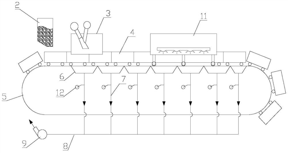
The invention discloses an oxygen-enriched and low-CO sintering method, an oxygen-enriched and low-CO sintering machine and a control method thereof. The oxygen-enriched and low-CO sintering machine includes: rails, trolleys, distributing machines, and bellows, and further includes: a CO concentration detection device , located in each of the bellows or branch flues; the oxygen-enriched air spraying device, located above the sintered material surface of the trolley, is configured to be able to move back and forth and adjust the length of the oxygen-enriched injection section, so as to be located at its oxygen-enriched Oxygen is sprayed on the surface of the sintered material in the injection section; the control device is used to control the injection amount of the oxygen-enriched air spraying device and the position and length of the oxygen-enriched injection section. The sintering method and sintering machine aim at the problems of large amount of flue gas treatment and high cost in the removal of CO from the existing sintering flue gas end. By spraying oxygen-enriched air to different areas of the sintering material surface, the full combustion of fuel is promoted, and the sintering process is reduced. The generation of CO can be controlled to realize the treatment of CO pollutants in sintering flue gas.

Description

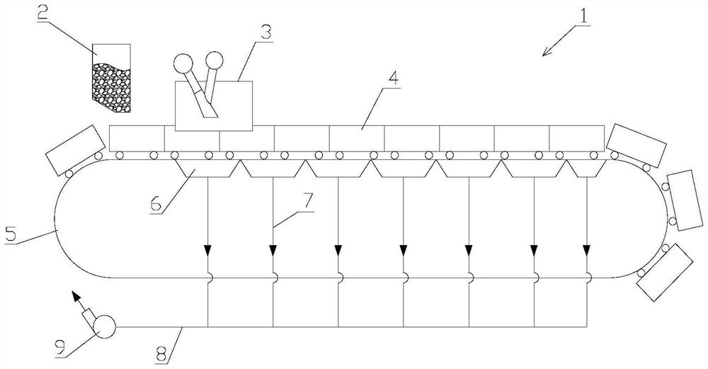
Oxygen-enriched and low-CO sintering method, oxygen-enriched and low-CO sintering machine and control method thereof technical field [0001] The present invention relates to the technical field of metallurgical equipment, especially an oxygen-enriched low-CO sintering machine. The invention also relates to control The method of the oxygen-enriched low-CO sintering machine. Background technique Sintering process is a key link in the ironmaking process, and its principle is to mix various powdery iron-containing raw materials into suitable Amount of fuel and flux, adding an appropriate amount of water, after mixing and pelletizing, the material will undergo a series of physical changes on the sintering equipment The chemical changes, sintered into a block, and then sent to the blast furnace for the next step. [0003] As shown in FIG. 1 , the sintering machine 1 is provided with a distributor 2 at the head, and an ignition furnace 3 is installed at the rear of the distri...

Claims


Application Information

Patent Timeline
Patent Type & Authority Patents(China)
IPC IPC(8): F27B9/40F27B9/30F27B9/16F27D7/02C22B1/16
CPCF27B9/40F27B9/3005F27B9/16F27D7/02C22B1/16F27M2003/04Y02P10/20
Inventor 廖继勇魏进超周浩宇刘前
Owner ZHONGYE-CHANGTIAN INT ENG CO LTD
Learn More