A method and system for estimating the beat signal frequency of fmcw laser ranging
A beat signal and laser ranging technology, which is applied to radio wave measurement systems, measuring devices, instruments, etc., can solve the problems of large amount of data processing calculations, slow frequency resolution speed, low frequency resolution, etc., to improve the frequency The effects of solving speed, improving frequency resolution, and reducing data processing amount
- Summary
- Abstract
- Description
- Claims
- Application Information
AI Technical Summary
Problems solved by technology
Method used
Image
Examples
specific Embodiment approach 1
[0027] Embodiment 1: This embodiment takes four-channel beat signals as an example, a method for estimating the frequency of FMCW laser ranging beat signals, including the following steps ( figure 2 ):
[0028] Step 1: Compressed sampling is performed on the beat signal to obtain a sampling value matrix after compression sampling ( image 3 ), including the following steps:
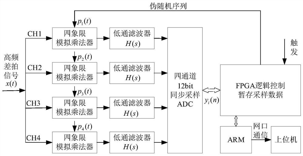
[0029] Step 11. The 4×511 random sequence generated by Matlab is stored in the ROM inside the FPGA, and then 4 different pseudo-random sequences are output by the FPGA (P 1 (t), P 2 (t), P 3 (t), P 4 (t));
[0030] Steps 1 and 2: Mix the generated pseudo-random sequence:
[0031] Using 4-channel four-quadrant analog multipliers to mix the pseudo-random sequence output by the FPGA with the four-channel beat signal to achieve the purpose of spreading in the frequency domain;
[0032] Step 13: Perform low-pass filtering on the beat signal processed in Steps 1 and 2:
[0033] The mixed signal passes ...
specific Embodiment approach 2
[0070] Embodiment 2: An FMCW laser ranging beat signal frequency estimation system includes: a compressed sampling module and a frequency estimation module;
[0071] The frequency estimation module is used for implementing the first embodiment;
[0072] The compression sampling module is used to compress and sample the original beat signal, including: an analog circuit module, an analog-to-digital conversion module, a digital control module, a communication module, and a trigger circuit;
[0073] The analog circuit module is composed of four-way four-quadrant analog multipliers and an eighth-order active low-pass filter (H(s)), which is used to mix and intercept the beat signal and the pseudo-random sequence, so as to achieve the The purpose of signal spread spectrum and weighted superposition to baseband;
[0074] The analog-to-digital conversion module is used to collect the beat signal compressed by the analog circuit module at a low sampling rate and convert it into a dig...
Embodiment
[0087] In practical application, the present invention realizes the frequency estimation of the center frequency of the beat signal in the range of 0-40 MHz, and the same compression sampling of 4 channels of hardware analog circuits. Among them, the number of symbols of the periodic pseudo-random sequence is set to M=511, and the system clock f of the periodic pseudo-random sequence is generated. sys = 80MHz, then the frequency of the periodic pseudo-random sequence is f p =f sys / M=156.556kHz, the cutoff frequency of the low-pass filter is f c =3f p / 2=234.833kHz, the sampling rate f of each channel s ≥2f c = 469.667kHz, then the ADC rate of each channel can realize the compressed sampling of the beat signal of 0-40MHz at 500kHz, and then estimate the frequency of the original beat signal according to the compressed and sampled beat signal to obtain the frequency of the beat signal . figure 1 The system block diagram of the frequency estimation of the beat signal gener...
PUM
 Abstract
Description
Claims
Application Information
 - R&D Engineer
- R&D Manager
- IP Professional
- Industry Leading Data Capabilities
- Powerful AI technology
- Patent DNA Extraction
Browse by: Latest US Patents, China's latest patents, Technical Efficacy Thesaurus, Application Domain, Technology Topic, Popular Technical Reports.
© 2024 PatSnap. All rights reserved.Legal|Privacy policy|Modern Slavery Act Transparency Statement|Sitemap|About US| Contact US: help@patsnap.com


