
Oil shale composite heating in-situ exploiting system and method

An in-situ mining and composite heating technology, which is applied in mining fluid, surface mining, underground mining, etc., can solve the problems of sealing failure, hindering the formation of heat injection, and excessive gas injection pressure, so as to achieve fewer underground accidents and increase Permeability, effect of long heating cycle

Active Publication Date: 2021-08-10
JILIN UNIV
View PDF8 Cites 6 Cited by
  • Summary
  • Abstract
  • Description
  • Claims
  • Application Information

AI Technical Summary

Problems solved by technology

[0006] The object of the present invention is to provide a system and method for oil shale composite heating in-situ mining in order to solve the problems raised in the above-mentioned background technology, which is used to solve the problems caused by uneven oil shale in the process of oil shale in-situ mining. The thermal expansion effect and kerogen coking caused by nature seriously hinder the formation of heat injection. The conventional downhole gas injection-heating integrated structure often has the problem of sealing failure caused by excessive gas injection pressure during operation, so as to improve heat injection efficiency and reduce Mining cost

Method used


Image

  • Oil shale composite heating in-situ exploiting system and method
  • Oil shale composite heating in-situ exploiting system and method
  • Oil shale composite heating in-situ exploiting system and method

Examples


Embodiment Construction

[0040] The following will clearly and completely describe the technical solutions in the embodiments of the present invention with reference to the accompanying drawings in the embodiments of the present invention. Obviously, the described embodiments are only some, not all, embodiments of the present invention. Based on the embodiments of the present invention, all other embodiments obtained by persons of ordinary skill in the art without making creative efforts belong to the protection scope of the present invention. In order not to obscure the essence of the present invention, well-known methods, procedures, procedures, components and circuits have not been described in detail.

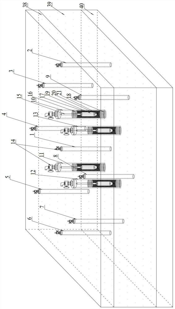
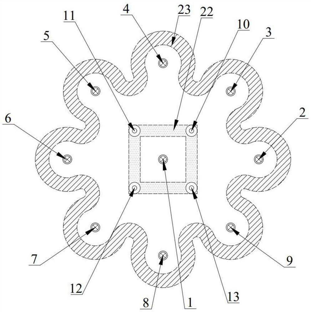
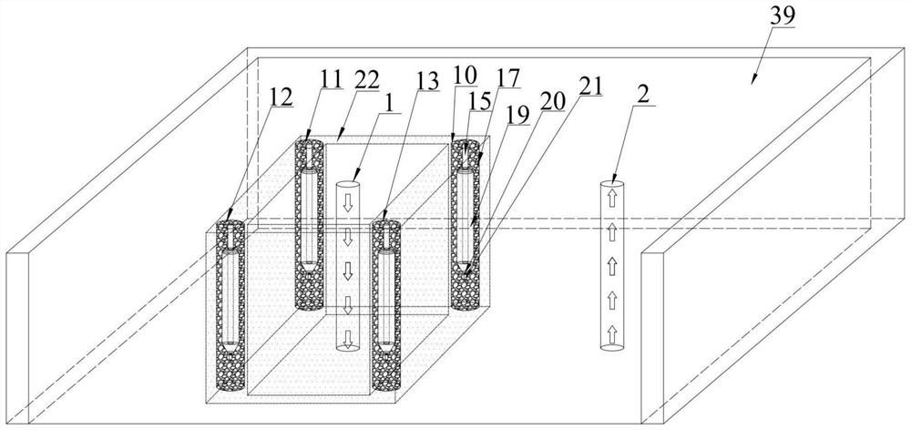
[0041] Such as figure 1 , figure 2 , image 3 and Figure 4 As shown, the oil shale composite heating in-situ recovery system includes: in-hole heating system, surface gas injection system, well pattern system and high-pressure breakdown system.

[0042] The heating system in the well includes...


PUM

PropertyMeasurementUnit
Thicknessaaaaaaaaaa
Thicknessaaaaaaaaaa
Thicknessaaaaaaaaaa

Abstract

The invention discloses an oil shale composite heating in-situ exploiting system and method, and belongs to the field of oil shale in-situ exploiting. The exploiting system comprises an in-well heating system, a ground gas injection system, a well pattern system and a high-pressure breakdown system; and the exploiting method exploits based on the oil shale composite heating in-situ exploiting system. According to the underground fixed heating-injection-production differentiation design, the problems of sealing failure, obvious corrosion and the like caused by too large pressure of a heating injection-production integrated structure are effectively solved, and heat loss along the way is effectively reduced through underground normal-temperature gas injection; a thermal wall effect is formed in the heating process of a heating well, and heating is stable and controllable; a breakdown electrode discharges in the high-pressure atmosphere at the bottom of the well to generate air gap breakdown, the permeability of an oil shale target layer is further improved, a heater is fixed in the well and subjected to underground gas injection combined construction, heat heats the stratum in a heat conduction and heat convection composite heating mode, the heat transfer effect is further improved, and the energy consumption-output ratio is remarkably reduced; and the in-situ exploiting period and the exploiting cost are further close to those of commercial exploiting.

Description

technical field [0001] The invention relates to the field of in-situ mining of oil shale, in particular to an oil shale composite heating in-situ mining system and method. Background technique [0002] As the exploration of unconventional energy resources such as oil shale, oil sands, oil-rich coal, coal bed methane and shale gas has been intensified in recent years, the proven reserves of unconventional energy resources are increasing year by year, and the exploration and application prospects are broad . [0003] Oil shale in-situ mining technology, also known as underground in-situ conversion technology, is to realize the exploitation of the target layer by injecting heat carrier medium into the target reservoir on the ground or downhole. The oil shale in the target interval undergoes hydraulic fracturing and shock wave fracturing technology to realize reservoir stimulation. The heat carrier medium exchanges heat with the oil shale in the target interval through conduct...

Claims


Application Information

Patent Timeline
IPC IPC(8): E21B43/24E21B43/16E21B43/14E21B43/30E21B43/295E21B43/26E21C41/24E21B33/13
CPCE21B43/2401E21B43/2405E21B43/168E21B43/14E21B43/30E21B43/295E21B43/26E21C41/24E21B33/13
Inventor 郭威朱斌李强王元卜青锋
Owner JILIN UNIV
Learn More