Conveying device for atrial shunt

A technology of a delivery device and a shunt, applied in the field of medical devices, can solve the problems of unnecessary functions, increased patient costs, complicated delivery devices, etc., and achieves the effects of low cost, alleviation of heart failure, and compact and ingenious structure.

Pending Publication Date: 2021-08-10
QICHEN (SHANGHAI) MEDICAL EQUIP CO LTD
View PDF16 Cites 1 Cited by
  • Summary
  • Abstract
  • Description
  • Claims
  • Application Information

AI Technical Summary

Problems solved by technology

[0007] One of the solutions in the existing technology is to implant an atrial shunt device, but the current delivery device specially used for the atrial shunt is too complicated, many functions are unnecessary, and the cost of the patient is increased. Therefore, it is necessary to simplify this to Eliminate functional redundancy in practical applications, reduce costs, and benefit patients

Method used


Image

  • Conveying device for atrial shunt
  • Conveying device for atrial shunt
  • Conveying device for atrial shunt

Examples


Embodiment 1

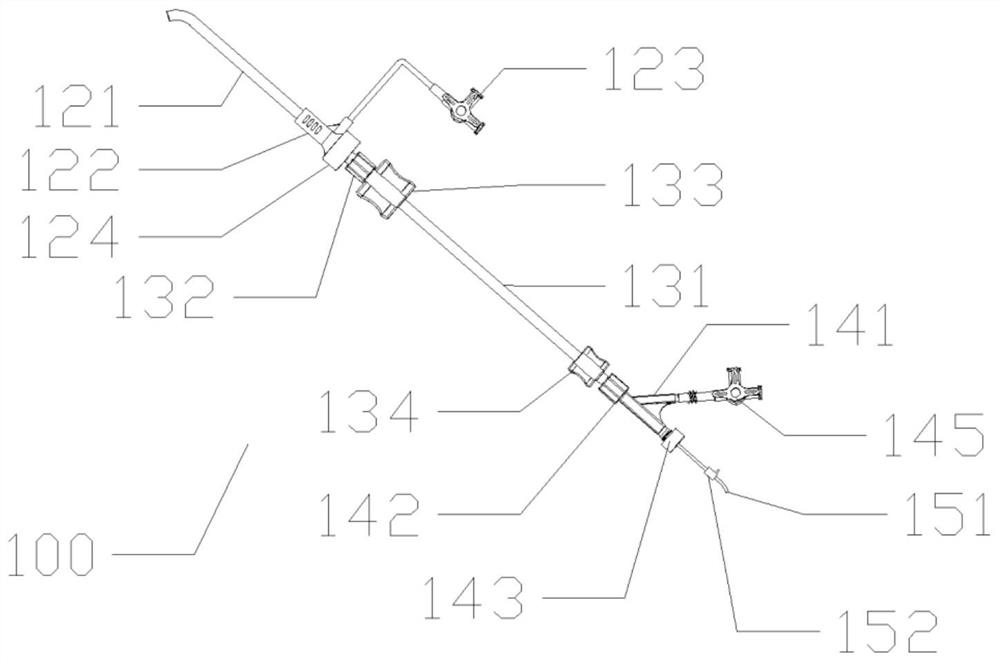
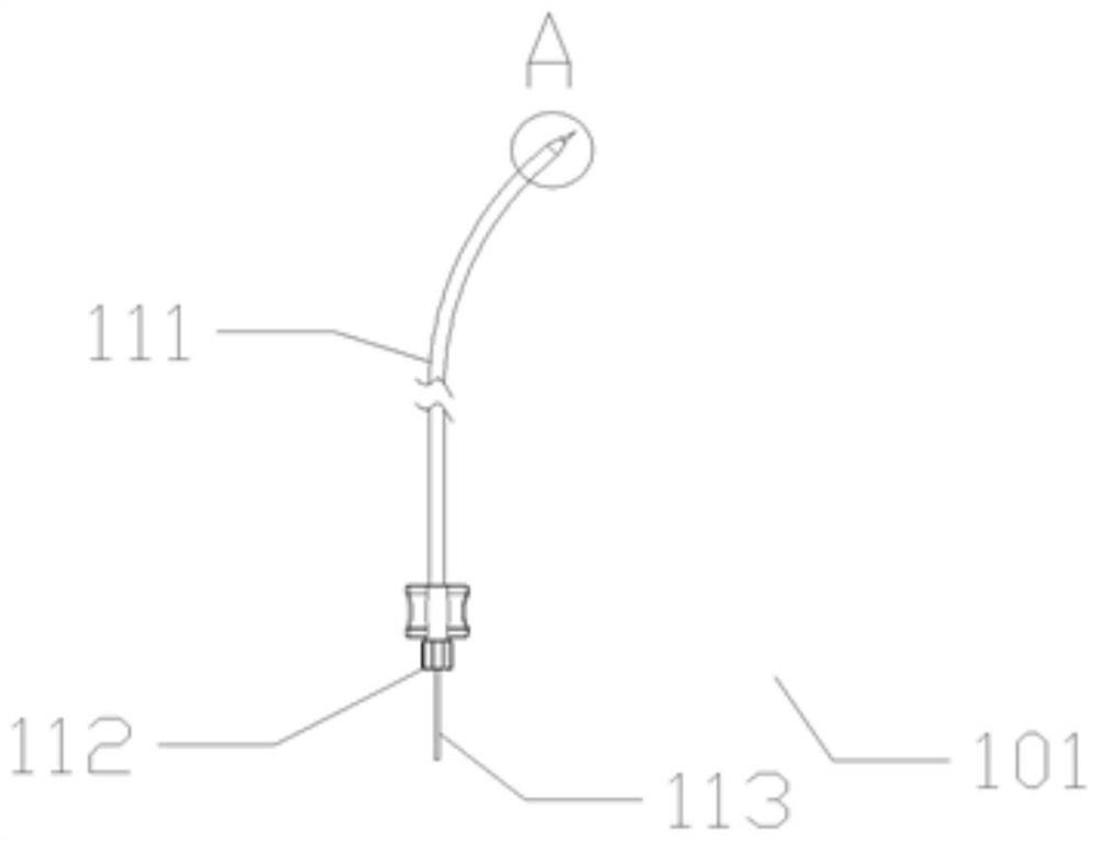
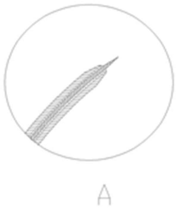
[0053] Embodiment one: if Figure 1 to Figure 16 As shown, the delivery system 100 of the atrial shunt of the present embodiment can help the atrial shunt 106 to pass through the "transseptal technique" (that is, the catheter is inserted into the right femoral vein, the inferior vena cava goes up and enters the right atrium. Then the septum is punctured And the catheter is passed into the left atrium) and sent to the interatrial septum 107 for atrial decompression. Specifically, the delivery system 100 of an atrial shunt consists of an expansion structure 101 , a delivery structure 102 , a loading structure 103 , an adjustable hemostatic structure 104 and a pushing structure 105 , and the loading structure 103 is connected to the delivery structure 102 and the adjustable hemostatic structure 104 . The expansion structure 101 is used to puncture and make a hole in the interatrial septum 107; the delivery structure 102 provides a shunt delivery channel to help the dilation cathe...

Embodiment 2

[0078] Embodiment two: if Figure 17 As shown, the difference between this embodiment and Embodiment 1 is that in this example, the adjustable hemostatic structure 104 and the loading structure 103 are combined into one, and the tail end 134 of the loading device is changed to an adjustable one with an emptying device and a silicone valve. Sealable tail end 134 ′, the structure of sealable tail end 134 ′ is similar to the handle of delivery structure 102 . The sealable tail end 134' is connected to the pushing structure 105.

Embodiment 3

[0079] Embodiment three: as Figure 18 As shown, the difference between this embodiment and Embodiment 1 is that: in this example, the annular boss 1224 on the conveying handle housing 122 in the conveying structure 102 is changed to a groove, and the annular groove 1241 is changed to a boss. The function of the delivery handle housing 122 is realized.


PUM


Abstract

The invention discloses a conveying device for an atrial shunt. The conveying device comprises an atrial shunt, an expansion structure used for atrial septum puncture and pore forming, a conveying structure providing a shunt conveying channel, a loading structure used for collecting the atrial shunt, an adjustable hemostasis structure used for preventing blood from flowing out and a pushing structure used for conveying the atrial shunt to the atrial septum and releasing the atrial shunt. The loading structure is connected with the conveying structure and the adjustable hemostasis structure, and the adjustable hemostasis structure is connected with the loading structure; the expansion structure comprises an expansion catheter and a puncture guide wire; the pushing structure comprises a pushing rod, and the conveying structure is formed by the expansion catheter, the puncture guide wire, the atrial shunt and the pushing rod to enter the heart position. The conveying device can help the atrial shunt to be successfully connected with the left atrium and the right atrium, reduces atrial pressure, prolongs the service life of the atrium, relieves heart failure, improves the success rate of surgery and the convenience of surgery operation, is beneficial to long-term health of a patient, and meanwhile is simple in structure and low in manufacturing cost.

Description

technical field [0001] The invention relates to the technical field of medical devices, in particular to a delivery device for an atrial shunt. Background technique [0002] Heart failure (heart failure), referred to as heart failure (HF), refers to the failure of the venous return blood to fully discharge the heart due to the impairment of the systolic function and / or diastolic function of the heart, resulting in blood stasis in the venous system and insufficient blood perfusion in the arterial system. , thus causing cardiac circulation disorder syndrome, which manifests as pulmonary congestion and vena cava congestion in this disorder syndrome cluster. Heart failure is not an independent disease, but the end stage of the development of heart disease. [0003] Heart failure can be divided into heart failure with preserved ejection fraction (HFpEF) and heart failure with reduced ejection fraction (HFrEF). HF patients are older, and the mortality rates caused by various type...

Claims


Application Information

Patent Timeline
IPC IPC(8): A61B17/00A61B17/34A61M39/06A61M25/10
CPCA61B17/3415A61B17/3468A61B17/0057A61M39/06A61M25/104A61M2039/062A61M2039/0626A61B2017/00575A61B2017/00623A61B2017/00606
Inventor 梁玉晨
Owner QICHEN (SHANGHAI) MEDICAL EQUIP CO LTD
Why Eureka
Try Eureka