Element joint and manufacturing method therefor
A component and component technology, applied in the field of component joints and its manufacturing, can solve problems such as damage, difficulty in expanding tubes of high-strength components, and difficulty in maintaining product shape
- Summary
- Abstract
- Description
- Claims
- Application Information
AI Technical Summary
Problems solved by technology
Method used
Image
Examples
no. 1 Embodiment approach
[0060] refer to figure 1 In the element joint 10 of this embodiment, a long pipe (first member) 11 formed of the material with the lowest strength, a short pipe (second member) 12 formed of a material with an intermediate strength, and a plate material ( 3rd part) 13 engagement.
[0061] Strength is mechanical strength, for example, it may be tensile strength or yield stress. The tensile strength will be described later as an example. In addition, the intermediate strength means that the strength is greater than or equal to the strength of the long pipe (first member) 11 and less than or equal to the strength of the plate (third member) 13 . That is, the short pipe (second member) 12 may be made of the same material as the long pipe (first member) 11 or the plate (third member) 33 . These also apply to the following embodiments.
[0062] The long tube 11 is in the shape of a long circular tube thinner than the short tube 12 . That is, the entire length of the long pipe 11...
no. 2 Embodiment approach
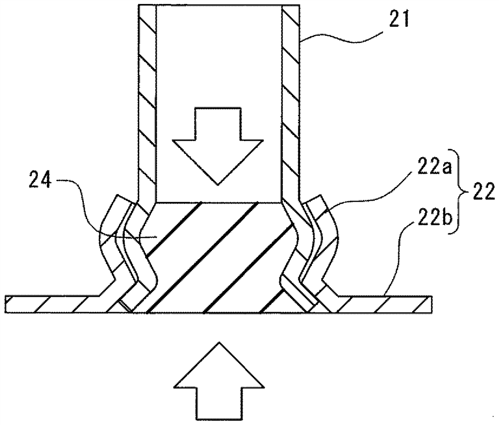
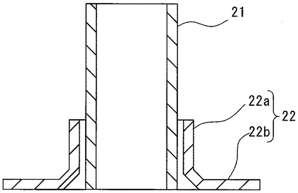
[0079] Figure 3A~3F with the first embodiment Figure 2A~2F Correspondingly, the manufacturing method of the element joint 10 of this embodiment is shown. In this embodiment, descriptions may be omitted for substantially the same parts as those in the first embodiment.
[0080] In the element joint 20 of this embodiment, a pipe (first member) 21 formed of the material with the lowest strength, a base (second member) 22 formed of the material with intermediate strength, and a plate (the third member) formed of the material with the highest strength are formed. Components) 23 are engaged.
[0081] The tube 21 is in the shape of an elongated circular tube thinner than the tubular portion 22 a of the pedestal 22 . The tube 21 is made of aluminum alloy, for example. The tensile strength of the aluminum alloy is about 400 MPa or less.
[0082] The pedestal 22 has a large-diameter and short cylindrical tubular portion 22a capable of being inserted into the tube 21 , and a flang...
no. 3 Embodiment approach
[0096] Figure 4 with the first embodiment Figure 2F Correspondingly, the element joint 30 of this embodiment is shown. In this embodiment, descriptions may be omitted for substantially the same parts as those in the first embodiment.
[0097] In the element joint 30 of this embodiment, a plate material (first member) 31 formed of the material with the lowest strength, a short pipe (second member) 32 formed of a material with intermediate strength, and a long pipe ( 3rd part) 33 is engaged.
[0098] The plate material 31 has a hole portion 31 a of a size capable of inserting the short pipe 32 . The plate material 31 is made of aluminum alloy, for example. The tensile strength of the aluminum alloy is about 400 MPa or less.
[0099] The short tube 32 is a circular tube with a large diameter and a short size to the extent that the long tube 33 can be inserted. That is, the entirety of the short tube 32 is a tubular portion. The short tube 32 is made of aluminum alloy, fo...
PUM
| Property | Measurement | Unit |
|---|---|---|
| tensile strength | aaaaa | aaaaa |
| tensile strength | aaaaa | aaaaa |
| tensile strength | aaaaa | aaaaa |
Abstract
Description
Claims
Application Information
 - Generate Ideas
- Intellectual Property
- Life Sciences
- Materials
- Tech Scout
- Unparalleled Data Quality
- Higher Quality Content
- 60% Fewer Hallucinations
Browse by: Latest US Patents, China's latest patents, Technical Efficacy Thesaurus, Application Domain, Technology Topic, Popular Technical Reports.
© 2025 PatSnap. All rights reserved.Legal|Privacy policy|Modern Slavery Act Transparency Statement|Sitemap|About US| Contact US: help@patsnap.com


