
Passive decoy state modulation reference system independent quantum key distribution system and method

A decoy state, reference frame technology, applied in the field of quantum cryptography, can solve the problems of security key distribution performance impact, side channel vulnerability, uneven probability distribution of photon number, etc., to improve marking efficiency, improve overall performance, and save resource overhead Effect

Pending Publication Date: 2021-08-06
AIR FORCE UNIV PLA
View PDF2 Cites 8 Cited by
  • Summary
  • Abstract
  • Description
  • Claims
  • Application Information

AI Technical Summary

Problems solved by technology

[0003] (1) The nonlinear crystal phase matching conditions are harsh, and its parametric down-conversion process is excited by random vacuum fluctuations, which is greatly affected by environmental factors, resulting in low conversion efficiency and prone to the problem of excessive code rate decay under long-distance conditions
[0004] (2) The detection efficiencies of the dual detectors used to detect idler light are not completely matched, resulting in fluctuations in the light intensity of the marker signal and uneven probability distribution of the number of photons, which affects the actual security key distribution performance
[0005] (3) The structure setting of the sender is relatively complicated, and it is easy to introduce side channel vulnerabilities
It is very difficult to completely distinguish the four kinds of marked light pulses and only three are used to modulate the decoy state, the resource utilization efficiency is not high, especially unfriendly to high-speed QKD systems

Method used


Image

  • Passive decoy state modulation reference system independent quantum key distribution system and method
  • Passive decoy state modulation reference system independent quantum key distribution system and method
  • Passive decoy state modulation reference system independent quantum key distribution system and method

Examples


Embodiment Construction

[0039] In order to make the object, technical solution and advantages of the present invention clearer, the present invention will be further described in detail below in conjunction with the accompanying drawings and embodiments. It should be understood that the specific embodiments described here are only used to explain the present invention, not to limit the present invention. In addition, the technical features involved in the various embodiments of the present invention described below may be combined with each other as long as they do not conflict with each other.

[0040] 1. Establish a passive decoy-state transmitter model based on weakly coherent light sources and linear crystals

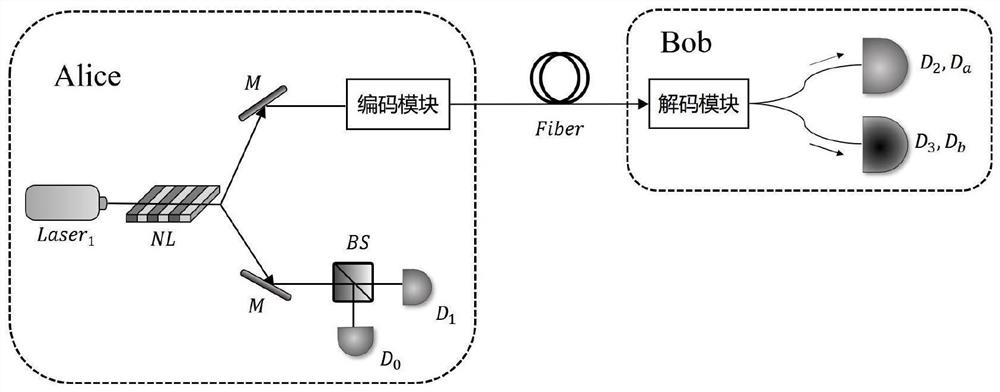
[0041] Such as figure 1 Shown is the nonlinear-based Schematic diagram of the QKD system independent of the passive decoy state reference frame of the crystal, including two parts: the Alice signal preparation device at the sending end and the Bob signal receiving and measuring device. ...


PUM


Abstract

The invention relates to a passive decoy state modulation reference system independent quantum key distribution system and method, and belongs to the technical field of quantum cryptography. The system comprises a transmitting end Alice signal preparation device and a Bob signal receiving and measuring device, wherein the transmitting end Alice signal preparation device comprises two pulse lasers Laser1 and Laser2, a beam splitter BS, a coding module and a threshold single-photon detector D0. The method comprises the following steps: describing QKD system parameters, and calculating a probability distribution rule of an Alice output signal of the transmitting end to determine a decoy state marking condition; respectively inputting a signal state and a decoy state into a coding module for modulation, wherein the coding module randomly selects one of three groups of mutually unbiased bases and codes key information on two intrinsic quantum states of each group of bases, a random coding mode is adopted and the result is sent to a receiving end Bob for measurement, base pairing screening, error correction and confidential amplification. The capability of the system for resisting rotation of a reference system is improved, and the overall key distribution performance is improved.

Description

technical field [0001] The invention belongs to the technical field of quantum cryptography, and specifically relates to a frame-independent Quantum Key Distribution (Quantum Key Distribution, QKD) method based on passive decoy state modulation, including a sending end setting method based on passive decoy state theory and a frame-independent QKD codec method. Background technique [0002] Quantum key distribution (QKD) relies on the quantum properties of single photons to encode, decode, transmit, receive, and post-process information, and can generate theoretically uneavesdropping and untamperable security keys between the two parties in communication. At present, the traditional QKD based on active decoy state modulation requires high-speed chopper control of the light source in hardware implementation, which not only consumes a lot of random number resources, but also increases the system's side channel security risks to a certain extent. In terms of software coding and...

Claims


Application Information

Patent Timeline
IPC IPC(8): H04L9/08H04B10/70
CPCH04L9/0852H04L9/0819H04B10/70
Inventor 薛阳石磊李佳豪
Owner AIR FORCE UNIV PLA
Learn More