Water flow alternation type cooling device for cooling tower

A cooling device and cooling tower technology, applied in water shower coolers, heat exchange equipment, heat exchanger types, etc., can solve problems such as water waste and achieve the effect of saving water resources

Active Publication Date: 2021-08-06
江西方舟流体科技有限公司
View PDF32 Cites 2 Cited by
  • Summary
  • Abstract
  • Description
  • Claims
  • Application Information

AI Technical Summary

Problems solved by technology

[0004] In order to overcome the shortcomings of using water as a coolant in cooling towers, a large amount of water will be wasted, and in order to reduce the waste of water sources, the technical problem is to provide a water rotation cooling device for cooling towers that can recycle water

Method used


Image

  • Water flow alternation type cooling device for cooling tower
  • Water flow alternation type cooling device for cooling tower
  • Water flow alternation type cooling device for cooling tower

Examples


Embodiment 1

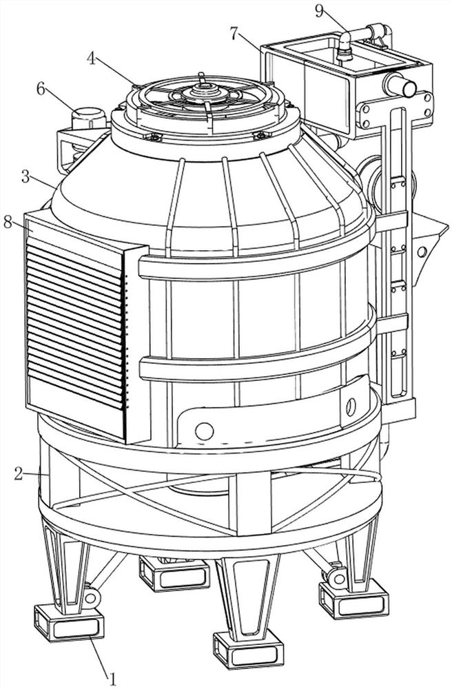
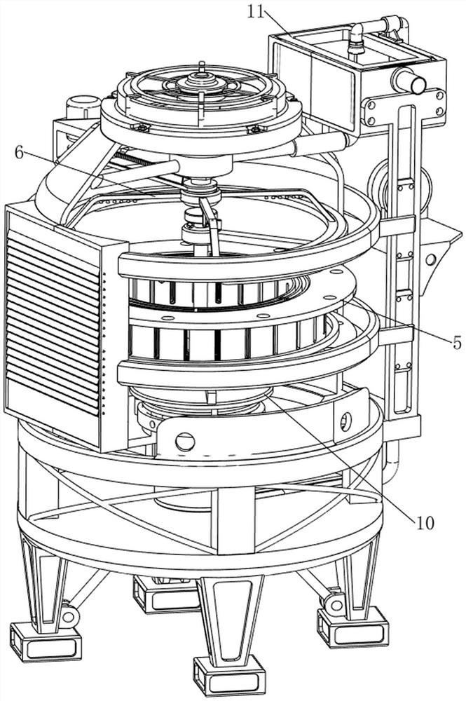
[0032] A water rotation cooling device for cooling towers, such as Figure 1-4 As shown, it includes a base 1, a support frame 2, a box body 3, a fan 4, a filler 5, a rotating mechanism 6, and a storage mechanism 7. The top of the base 1 is provided with a support frame 2, and the top of the support frame 2 is provided with a box body 3. A filler 5 is arranged in the middle of the inner wall of the body 3 , a fan 4 is connected in the middle of the top of the box body 3 , a rotating mechanism 6 is arranged on the box body 3 , and a storage mechanism 7 is arranged between the box body 3 and the rotating mechanism 6 .

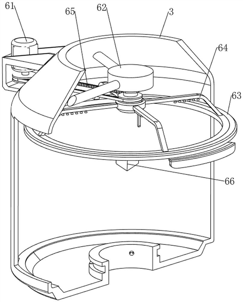
[0033] The rotating mechanism 6 includes a motor 61, the first water tank 62, a fixed mount 63, a rotary nozzle 64, a belt 65 and a lower pressing block 66, the upper left side of the casing 3 is provided with a motor 61, and the inner upper side inwall of the casing 3 is provided with a first Water tank 62, the inner wall of the upper side of the box body 3 is p...

Embodiment 2

[0037] On the basis of Example 1, such as Figure 5-14 As shown, a heat dissipation mechanism 8 is also included. The heat dissipation mechanism 8 includes a rotating plate 81, a first connecting rod 82, a second connecting rod 83, a first compression spring 84, an electromagnet 85 and a neodymium magnet 86. The front side of the box body 3 The middle evenly rotates and is connected with a rotating plate 81, and the rotating plate 81 is longitudinally distributed. The left and right sides between two adjacent rotating plates 81 are provided with first connecting rods 82, and the rear of the third rotating plate 81 from top to bottom The second connecting rod 83 is arranged in the middle of the side, and the second connecting rod 83 is in contact with the lower pressing block 66. The left and right sides of the upper inner wall of the front side of the box body 3 and the rear left and right sides of the third rotating plate 81 from top to bottom First compression springs 84 are...


PUM


Abstract

The invention relates to a cooling device, in particular to a water flow alternation type cooling device for a cooling tower. The water flow alternation type cooling device for the cooling tower can recycle water. According to the technical scheme, the water flow alternation type cooling device for the cooling tower comprises a base, a supporting frame, a box body, a fan, filler, a rotating mechanism and a storage mechanism, the supporting frame is arranged at the top of the base, the box body is arranged at the top of the supporting frame, the filler is arranged in the middle of the inner wall of the box body, the fan is connected to the middle of the top of the box body, the rotating mechanism is arranged on the box body, and the storage mechanism is arranged between the box body and the rotating mechanism. Through cooperation of the rotating mechanism and the storage mechanism, water flow in a water storage tank is pumped into a first water tank, then the water flow drips onto the filler through a rotating spray head, in the way, the filler is wetted, and the draught fan operates.

Description

technical field [0001] The invention relates to a cooling device, in particular to a water flow rotation cooling device for cooling towers. Background technique [0002] The cooling tower is a device that uses water as a circulating coolant to absorb heat from the system and discharge it to the atmosphere to reduce the water temperature. It uses water and air to exchange heat and cold to generate steam. The steam volatilizes and takes away heat to achieve evaporation and heat dissipation. The principle of heat transfer and radiation heat transfer is used to dissipate the waste heat generated in the industry or in refrigeration and air conditioning to reduce the water temperature of the evaporative heat dissipation device to ensure the normal operation of the system. The device is generally barrel-shaped, so it is called a cooling tower. [0003] The use of water as a coolant in cooling towers will cause a lot of water waste. In order to reduce the waste of water sources, we ...

Claims


Application Information

Patent Timeline
IPC IPC(8): F28C1/00F28F25/06F28F25/08F28F25/10F28F27/00
CPCF28C1/00F28F25/08F28F25/06F28F25/10F28F27/003Y02B30/70
Inventor 周武平谢茂华
Owner 江西方舟流体科技有限公司
Why Eureka
Try Eureka