
Garbage pyrolysis gasification treatment device

A technology of pyrolysis gasification and treatment device, applied in grain treatment, packaging, transportation and packaging, etc., can solve the problems of waste gas affecting natural ecology and environmental protection, damage to recyclable items, waste of limited material resources, etc., to achieve convenient Sorting processing, convenient secondary processing, and the effect of enhancing practicality

Active Publication Date: 2021-08-06
上海艾尔天合环境科技有限公司
View PDF6 Cites 1 Cited by
  • Summary
  • Abstract
  • Description
  • Claims
  • Application Information

AI Technical Summary

Problems solved by technology

[0005] Aiming at the deficiencies of the prior art, the present invention provides a garbage pyrolysis gasification treatment device, mainly to solve the problem of poor sorting effect of garbage, resulting in damaged or seriously polluted recyclable items and limited waste. Material resources and the waste gas produced at the same time affect the natural ecology and environmental protection

Method used


Image

  • Garbage pyrolysis gasification treatment device
  • Garbage pyrolysis gasification treatment device
  • Garbage pyrolysis gasification treatment device

Examples


Embodiment 1

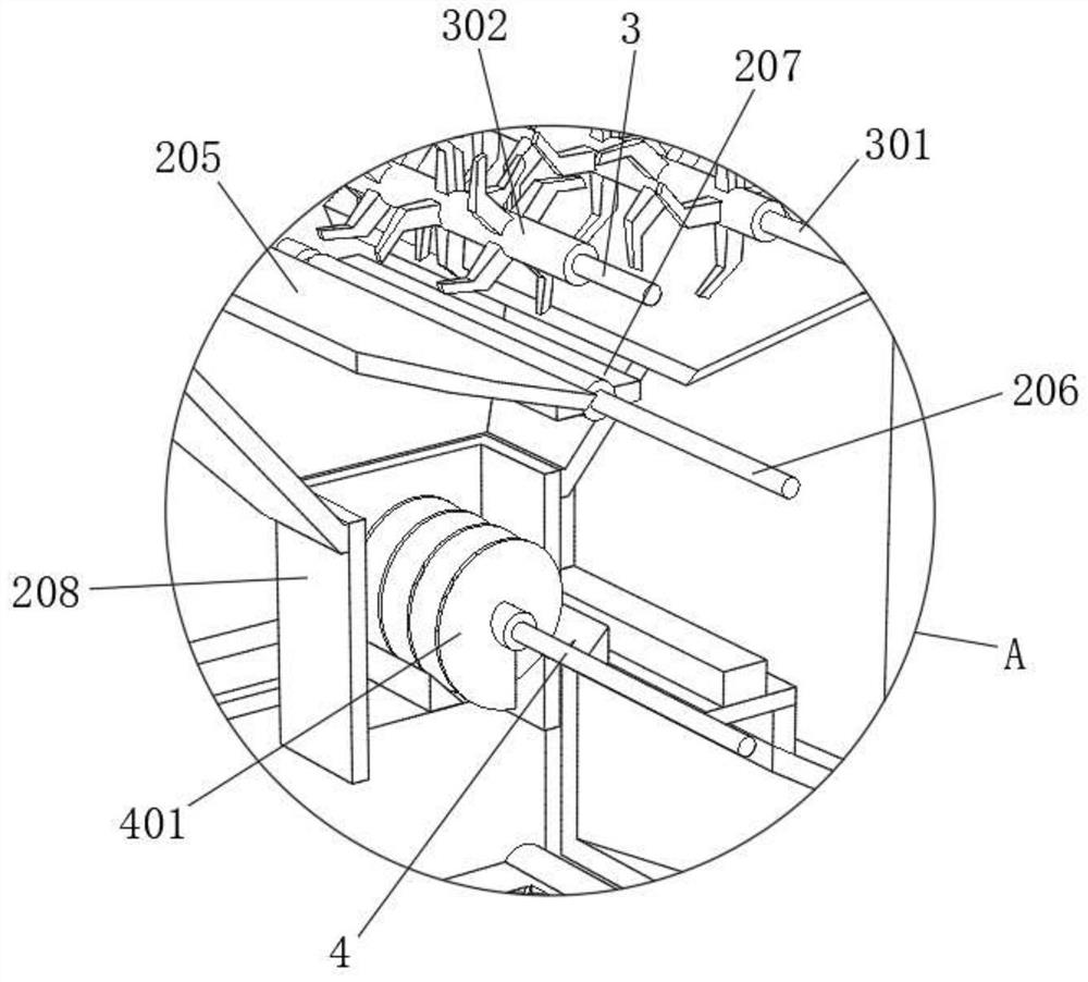
[0035] refer to Figure 1-Figure 6 , a garbage pyrolysis gasification treatment device, comprising a base plate 1, the upper surface of the base plate 1 is fixed with a frame 2 by bolts, the upper surface of the frame 2 is fixed with a treatment box 201 by bolts, and the upper surface of the treatment box 201 is provided with a feed inlet , the upper surface of the feed inlet is fixed with a hollow plate 202 by bolts, the upper surface of the hollow plate 202 is fixed with a support frame 203 by bolts, the inner wall of the support frame 203 is fixed with the same storage bucket 204 by bolts, and the bottom of the storage bucket 204 is provided with a discharge In the discharge port, a discharge cylinder 208 is fixed by bolts, and the inner walls of both sides of the storage bucket 204 are rotatably connected with a driving shaft 3, a driven shaft 301 and a rotating rod 206, and one side of the rotating rod 206 is provided with a first belt 305 and a second belt. Two belts 402...

Embodiment 2

[0039] refer to Figure 7 , the upper surface of the processing barrel 7 is fixed with a supporting arc plate 11 by bolts, and the upper surface of the supporting arc plate 11 is fixed with a hot air blower 1101 by bolts, and the garbage in the processing barrel 7 is dried and heated by the hot air blower 1101 on the supporting arc plate 11. Chemical treatment, avoiding the adhesion of non-metallic garbage, facilitating the transfer of garbage in the treatment barrel 7 by the transfer mechanism, and improving the efficiency of the device's operation and processing. The upper surface of the bottom plate 1 is provided with a storage box 12, and the outer wall of the storage box 12 is provided with a seal The bottom of the sealing port is rotatably connected with a sealing plate 1201, and the multi-side inner wall of the storage box 12 is fixed with the same partition 1202 by bolts, and the cooperation of the storage box 12 and the partition 1202 can concentrate the metal scraps o...


PUM


Abstract

The invention relates to the technical field of garbage treatment equipment, and discloses a garbage pyrolysis gasification treatment device which comprises a bottom plate. A machine frame is fixedly connected to the upper surface of the bottom plate, a treatment box is fixedly connected to the upper surface of the machine frame, a feeding port is formed in the upper surface of the treatment box, and a hollowed-out plate is fixedly connected to the upper surface of the feeding port; and a supporting frame is fixedly connected to the upper surface of the hollowed-out plate, a same storage hopper is fixedly connected to the inner walls of multiple sides of the supporting frame, a discharging port is formed in the bottom of the storage hopper, a discharging barrel is fixedly connected into the discharging port, a driving shaft, a driven shaft and a rotating rod are rotatably connected to the inner walls of the two sides of the storage hopper, and the two ends of the driving shaft, the two ends of the driven shaft and the two ends of the rotating rod penetrate through the outer walls of the two sides of the storage hopper. Rotating blades cut the outer surface of garbage, the garbage can be conveniently treated by the rotating blades, the garbage can be uniformly transferred through an inclined plate and a rotating plate, blockage caused by garbage classification treatment is avoided, large garbage can be cut, bottle and can garbage can be cut, and liquid in the bottle and can garbage can be concentrated.

Description

technical field [0001] The invention relates to the technical field of garbage treatment equipment, in particular to a garbage pyrolysis gasification treatment device. Background technique [0002] There are generally two ways of traditional garbage disposal: one is deep burial treatment, which will lead to pollution and waste of land resources. At the same time, it takes a long time for garbage to decompose, which is not suitable for long-term treatment. The other is incineration, which is not suitable for incineration because there are many substances in the garbage that cannot be burned and produce harmful gases. At the same time, the renewable resources in the garbage are not suitable for incineration. Therefore, we need a device that can classify garbage and fully pyrolyze and gasify it, so as to reduce the pollution of garbage to the environment. [0003] At present, most of the existing garbage pyrolysis and gasification treatment devices have the following deficienc...

Claims


Application Information

Patent Timeline
Patent Type & Authority Applications(China)
IPC IPC(8): B09B3/00B09B5/00B65B69/00B02C21/00B02C18/14B02C18/24B02C18/22B02C23/08
CPCB09B3/00B09B5/00B65B69/0033B02C21/00B02C18/14B02C18/24B02C18/2225B02C23/08B09B2101/02B09B3/40
Inventor 李玲
Owner 上海艾尔天合环境科技有限公司
Learn More