Vacuum cleaner

A technology for vacuum cleaners and suction openings, which is applied in the direction of vacuum cleaners, suction filters, robot cleaning machines, etc., and can solve the problems of users being exposed to dust, etc.

Pending Publication Date: 2021-08-06
VORWERK & CO INTERHOLDING GMBH
View PDF0 Cites 0 Cited by
  • Summary
  • Abstract
  • Description
  • Claims
  • Application Information

AI Technical Summary

Problems solved by technology

[0005] The disadvantage here is that the user comes into contact with dust and / or dirt, which is especially problematic for allergy sufferers

Method used


Image

  • Vacuum cleaner
  • Vacuum cleaner
  • Vacuum cleaner

Examples


Embodiment Construction

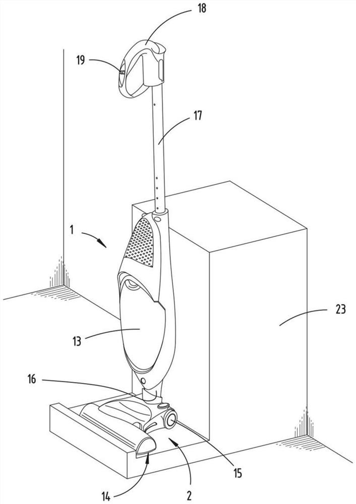
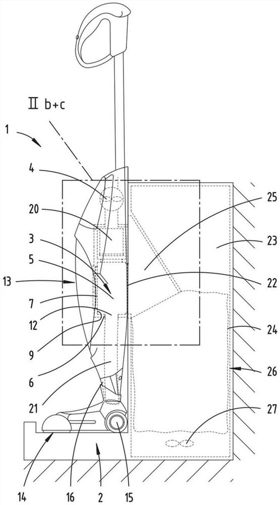
[0029] figure 1 A vacuum cleaner 1 disposed on the base station 23 is shown. The vacuum cleaner 1 is exemplarily designed as a hand-held vacuum cleaner 1, which has a base apparatus 13 and a nozzle 2 as a detachable attachment. The suction mouth 2 has a suction port 14, and the suction can be sucked into the vacuum cleaner 1 to be cleaned by the suction port 14. In order to facilitate the movement of the vacuum cleaner 1 to move on the surface to be cleaned, the suction nozzle 2 has a wheel 15. The base apparatus 13 and the nozzle 2 are detachably connected to each other by the connection region 16 such that the suction nozzle 2 may be alternatively replaced with other nozzle 2. On the base device 13 having a handle 17 with a handle 18, the user can guide the vacuum cleaner 1 on the surface to be cleaned by the handle 17. This is usually carried out in successive back-to-back motion. The handle 17 is preferably a telescopically, allowing the user to adjust the height of the handl...


PUM


Abstract

The invention relates to a vacuum cleaner having a suction nozzle, a suction object chamber and a fan which are fluidically connected to one another and fluidically connected to one another such that during a suction operation of the vacuum cleaner, a suction object is sucked into the suction object chamber by means of the fan via the suction nozzle, the suction substance chamber has a chamber housing defining a suction substance receiving region, the suction substance chamber has an emptying opening through which the suction substance can exit the suction substance chamber during the regeneration operation. The suction chamber has at least one thrust element (7) which can be reversibly moved into the suction receiving region (5) relative to the suction receiving region (5) and which is reversibly variable in size, said thrust element delimiting at least one partial region of the maximum volume of the suction receiving region (5) which can be used to receive the suction, the displacement and / or dimensional change of the thrust element (7) reduces the volume available during the regeneration operation, which results in a displacement of the suction material inside the suction material chamber (3) in the direction of the emptying opening (8) of the suction material chamber (3).

Description

Technical field [0001] The present invention relates to a vacuum cleaner having a nozzle, a suction cavity, and a fan, the suction, the suction cavity, and the fan in fluid communication, so that the suction during the suction operation of the vacuum cleaner is used by the fan. Suction into the suction chamber, wherein the suction cavity has a cavity casing that defines a boundary of the suction area, and wherein the suction cavity has a clear opening, the suction can be emptied during the regeneration operation. The opening leaves the suction cavity. Background technique [0002] The vacuum cleaner of the aforementioned type is well known in the art. [0003] Further, for example, a dust-free bag vacuum cleaner is known which construct a cyclone vacuum cleaner or a so-called permanent filter, which can regenerate and reuse the accumulated suction. In order to empty the suction cavity or is known for the regenerative permanent filter, or open the vacuum cleaner over the collectio...

Claims


Application Information

Patent Timeline
Patent Type & Authority Applications(China)
IPC IPC(8): A47L5/30A47L9/00A47L9/10
CPCA47L5/30A47L9/00A47L9/10A47L2201/024A47L9/106A47L9/127A47L9/2873
Inventor H-P.阿诺尔德J.贝尔豪森I.埃林
Owner VORWERK & CO INTERHOLDING GMBH
Why Eureka
Try Eureka