
A safety liquid discharge device and method for gas inlet and outlet gas system of aspirator

A technology of a gas system and a liquid drainage device, which is applied in the field of coking, can solve the problems of waste gas emission, environmental pollution, and difficulty in dredging.

Active Publication Date: 2022-07-22
宣化钢铁集团有限责任公司
View PDF15 Cites 0 Cited by
  • Summary
  • Abstract
  • Description
  • Claims
  • Application Information

AI Technical Summary

Problems solved by technology

During the transportation of coke oven gas, the body of the aspirator and its front and rear gas pipelines will produce a large amount of condensate. If the condensate cannot be discharged in time, it will not only seriously affect the transportation of coke oven gas, but also cause waste gas to disperse, pollute the environment, and accumulate The condensate in the gas delivery system will also cause the aspirator body to surge, which is not conducive to the efficient and safe operation of the aspirator
[0003] At present, the gas system at the inlet and outlet of the gas suction body generally uses a normally open manual shut-off door to drain the condensate generated to the underground liquid seal tank for recycling. Poor liquid drainage often occurs, which seriously affects the normal transportation of coke oven gas and the safe operation of the aspirator. Therefore, the traditional method of condensate discharge can no longer meet the requirements of safe transportation of coke oven gas in coking enterprises. Safe and reliable suction machine inlet and outlet gas system draining device and draining method is very necessary

Method used


Image

  • A safety liquid discharge device and method for gas inlet and outlet gas system of aspirator

Examples


Embodiment Construction

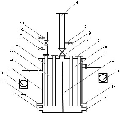
[0038] The invention provides a safe liquid draining device and method for the inlet and outlet gas system of the aspirator, which can continuously discharge a large amount of condensate generated during the coke oven gas delivery process from the inlet and outlet gas systems of the aspirator to production. The recovery system ensures that the inlet and outlet gas systems of the suction body are unobstructed, which is conducive to the pumping of coke oven gas for external supply. This method has the characteristics of standardization and standardization of operation steps, which can guide the post operators to carry out scientific operations, improve the operation efficiency, obtain the best operation effect, and solve the safety problems caused by blind operation.

[0039] see figure 1 , the safety liquid discharge device of the present invention includes a tank body 1, two front liquid discharge pipes 2, two rear liquid discharge pipes 4, a discharge pipe 6, a discharge cont...


PUM


Abstract

The invention discloses a safety liquid discharge device for an inlet and outlet gas system of an aspirator, comprising a tank body, a liquid discharge pipe at the front of the machine, and a liquid discharge pipe at the rear of the machine. The inner cavity is divided into the front liquid sealing tank and the rear liquid sealing tank by the partition plate; the upper part of the side wall of the front liquid sealing tank and the rear liquid sealing tank pass through the front full flow pipe and the rear full flow pipe respectively and collect underground. The lower ends of the front liquid discharge pipe and the rear liquid discharge pipe respectively extend into the front liquid sealing groove and the bottom of the rear liquid sealing groove, and the upper ends are respectively connected with the bottom of the liquid discharge funnel of the inlet and outlet gas system of the suction body. The liquid discharge cutoff is connected, and the front end and the rear end of the liquid discharge cutoff are connected with the steam pipe network through the steam sweep cutoff. The invention utilizes the tank to collect and discharge the condensate produced by the gas system, which can not only realize the continuous discharge of the condensate, but also regularly purge the liquid discharge pipeline, so that the condensate can be discharged in time, which provides a good solution for coke oven production and gas transportation. Strong guarantee.

Description

technical field [0001] The invention relates to a device and a method for safely discharging a large amount of condensate produced by an inlet and outlet gas system of an aspirator, and belongs to the technical field of coking. Background technique [0002] The waste gas produced in the high-temperature coking production process of coking enterprises is first washed and absorbed by the full negative pressure (or semi-negative pressure) gas purification system, and then the clean gas is pumped to the gas users by the high-speed aspirator. In the process of coke oven gas transportation, a large amount of condensate will be produced in the suction machine body and its front and rear gas pipelines. If these condensate cannot be discharged in time, it will not only seriously affect the coke oven gas transportation, but also cause waste gas to be released, pollute the environment, and accumulate. The condensate in the gas delivery system will also cause the suction body to surge, ...

Claims


Application Information

Patent Timeline
Patent Type & Authority Patents(China)
IPC IPC(8): F17D3/14F17D3/01
CPCF17D3/145F17D3/01
Inventor 钟继生孙风江王景荣张强熊建新郭有林陈友白剑锋郭豪有黄丽虹
Owner 宣化钢铁集团有限责任公司
Learn More