
Liquid crystal panel layering detection equipment and method

A liquid crystal panel and detection equipment technology, which is applied in the field of liquid crystal panel layered detection equipment, can solve problems affecting the detection effect, etc., and achieve the effects of ensuring the accuracy of photography, increasing product yield, and reducing scrap products

Active Publication Date: 2021-07-27
HEFEI SHANGJU IND EQUIP +2
View PDF8 Cites 3 Cited by
  • Summary
  • Abstract
  • Description
  • Claims
  • Application Information

AI Technical Summary

Problems solved by technology

The automatic detection device in the prior art cannot realize the real physical layer of the detected defect and whether it is the surface dust that was not filtered out during the detection, which greatly affects the final detection effect

Method used


Image

  • Liquid crystal panel layering detection equipment and method
  • Liquid crystal panel layering detection equipment and method
  • Liquid crystal panel layering detection equipment and method

Examples


Embodiment Construction

[0047] In order to make the purpose, technical solutions and advantages of the embodiments of the present invention clearer, the technical solutions in the embodiments of the present invention will be clearly and completely described below in conjunction with the accompanying drawings in the embodiments of the present invention. Obviously, the described embodiments It is some embodiments of the present invention, but not all of them. Based on the implementation manners in the present invention, all other implementation manners obtained by persons of ordinary skill in the art without creative efforts fall within the protection scope of the present invention. Accordingly, the following detailed description of the embodiments of the invention provided in the accompanying drawings is not intended to limit the scope of the claimed invention, but merely represents selected embodiments of the invention. Based on the implementation manners in the present invention, all other implement...


PUM


Abstract

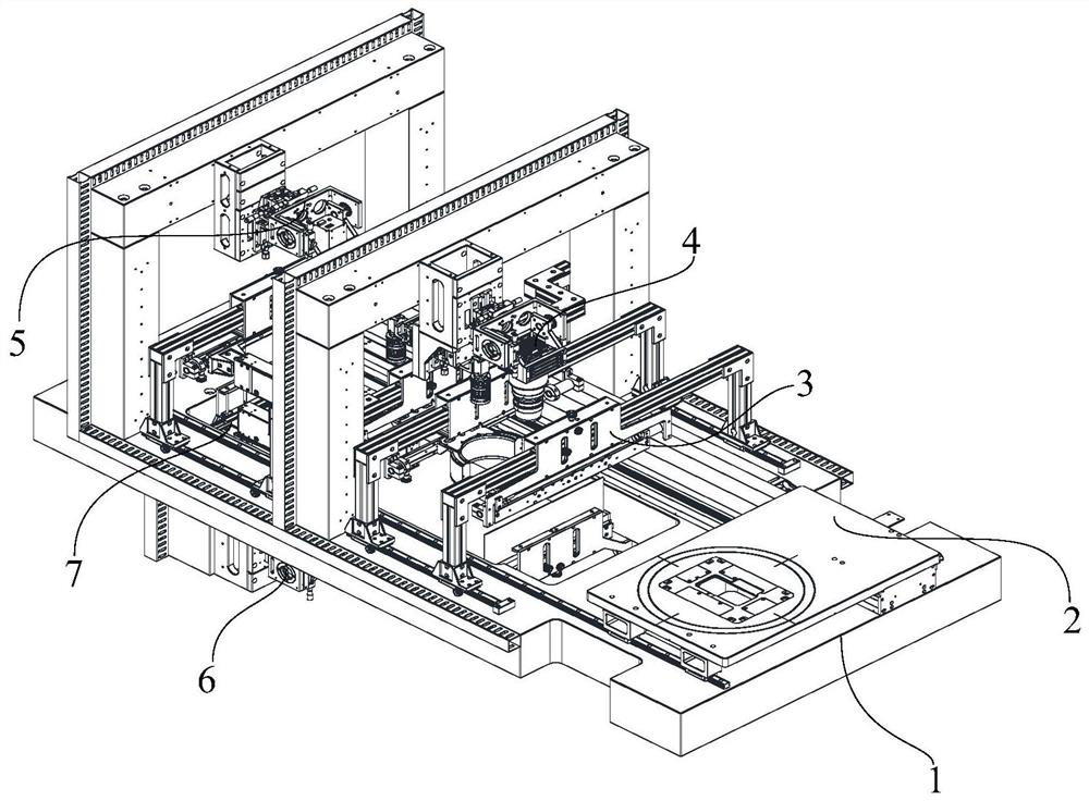
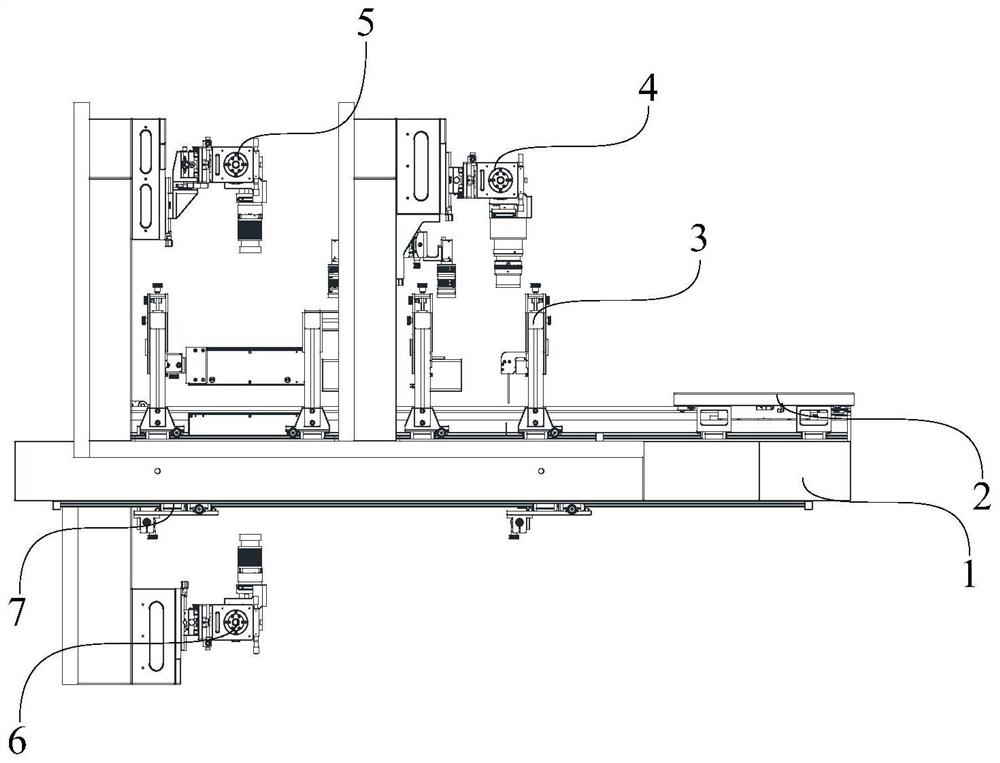
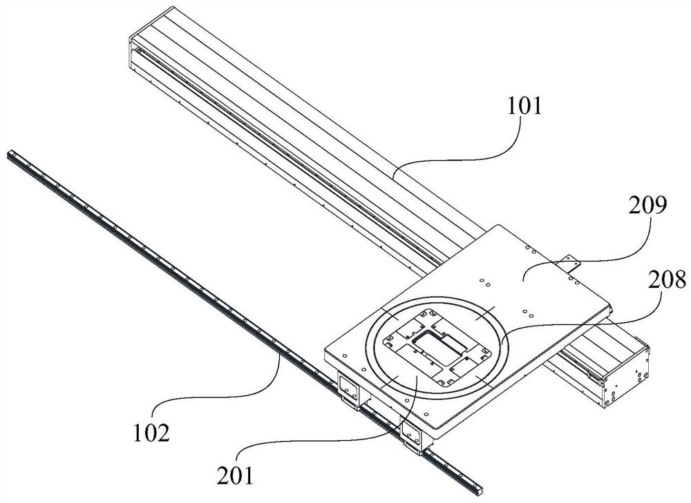
The invention provides (a) liquid crystal panel layering detection equipment and method. The equipment comprises a base, a movable carrying table, a natural light source camera assembly, a first ultraviolet light source camera assembly, a second ultraviolet light source camera assembly, an upper light source assembly and a backlight source assembly, the movable carrying table is an air floating platform and is arranged above the base, the natural light source camera assembly, the upper light source assembly and the first ultraviolet light source camera assembly are all located at one side of the movable carrying table, the first ultraviolet light source camera assembly and the second ultraviolet light source camera assembly are symmetrically arranged with the liquid crystal panel as the axis, and the second ultraviolet light source camera assembly and the backlight source assembly are both located on the other side of the liquid crystal panel; the upper light source assembly comprises a first natural light source assembly and a first ultraviolet light source assembly, and the backlight source assembly comprises a second natural light source assembly and a second ultraviolet light source assembly. The defects on the surface of the liquid crystal panel and the defects in the liquid crystal panel can be automatically distinguished, and the detection efficiency is improved.

Description

technical field [0001] The present invention relates to the technical field of liquid crystal panel delamination detection equipment, in particular to a liquid crystal panel delamination detection equipment and method. Background technique [0002] The typical composition of LCD (Liquid Crystal Display) liquid crystal screen is TP (Touch Panel, touch screen) glass, upper polarizer, color filter, liquid crystal layer, TFT (Thin Film Transistor, thin film transistor) substrate, lower polarizer from top to bottom and backlight. With the development of LCD technology, it has quickly become the leading role in the display market due to its characteristics of high resolution, small size, light weight, no radiation, flat panel and low power consumption. From mobile phones to portable game consoles, from industrial equipment to artificial LCD is ubiquitous in many fields such as operating platform to bank self-service equipment ATM (Automatic Teller Machine). Therefore, it becomes...

Claims


Application Information

Patent Timeline
IPC IPC(8): G01N21/95G01N21/01
CPCG01N21/95G01N21/8851G01N21/01G01N2021/9513G01N2021/8887G01N2021/8854G01N2021/8861
Inventor 杨洋黄斌
Owner HEFEI SHANGJU IND EQUIP
Learn More