
Reductant spray device, exhaust gas processing device, and exhaust gas processing method

A technology of injection device and reducing agent, which is applied in the direction of electronic control, exhaust treatment, and noise reduction device of exhaust gas treatment device, can solve the problems of temperature reduction and uneven temperature of honeycomb structure, and achieve the effect of less power consumption

Active Publication Date: 2021-07-23
NGK INSULATORS LTD
View PDF15 Cites 0 Cited by
  • Summary
  • Abstract
  • Description
  • Claims
  • Application Information

AI Technical Summary

Problems solved by technology

[0006] However, when the urea aqueous solution is sprayed in mist form to the honeycomb structure portion heated by energization, the temperature of the area where the urea aqueous solution is sprayed in the mist form decreases, and the honeycomb structure Internal temperature unevenness

Method used


Image

  • Reductant spray device, exhaust gas processing device, and exhaust gas processing method
  • Reductant spray device, exhaust gas processing device, and exhaust gas processing method
  • Reductant spray device, exhaust gas processing device, and exhaust gas processing method

Examples


Embodiment approach 1

[0044] (1) Reductant injection device

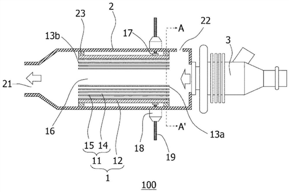
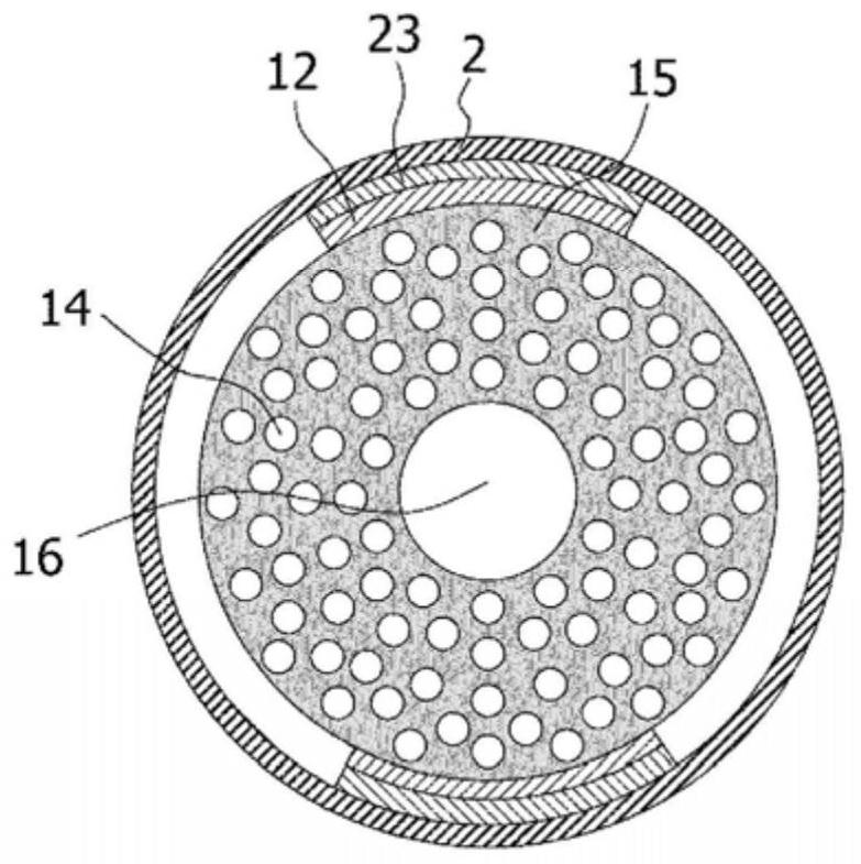
[0045] figure 1 It is a schematic sectional view showing the reducing agent injection device according to Embodiment 1 of the present invention (a schematic sectional view parallel to the direction in which the cells of the honeycomb structure portion extend). in addition, figure 2 yes figure 1 A schematic cross-sectional view of line AA' in (a schematic cross-sectional view perpendicular to the direction in which the cells of the honeycomb structure part extend).

[0046] Such as figure 1 and figure 2 As shown, the reducing agent injection device 100 of the present embodiment includes: a honeycomb structure 1 ; an outer cylinder 2 that accommodates the honeycomb structure 1 ; and a urea sprayer 3 disposed at one end of the outer cylinder 2 .

[0047] The honeycomb structure 1 has: a columnar honeycomb structure portion 11 having a partition wall 15 defining a plurality of compartments 14 extending from a fluid inflow end surface 13...

Embodiment approach 2

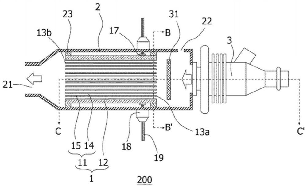
[0132] image 3 It is a schematic sectional view showing the reducing agent injection device according to Embodiment 2 of the present invention (a schematic sectional view parallel to the direction in which the cells of the honeycomb structure portion extend). in addition, Figure 4 yes image 3 A schematic cross-sectional view of the line BB' in (a schematic cross-sectional view perpendicular to the direction in which the cells of the honeycomb structure part extend), Figure 5 yes image 3 A schematic cross-sectional view of line CC' in (a schematic cross-sectional view parallel to the direction in which the cells of the honeycomb structure part extend).

[0133] Such as Figure 3 ~ Figure 5 As shown, in the reducing agent injection device 200 of the present embodiment, the honeycomb structure 1 having the quadrangular columnar honeycomb structure 11 is accommodated in the outer cylinder 2, and in the outer cylinder 2, the second flow path (the space region 16 ) is form...

Embodiment approach 3

[0138] Image 6 and Figure 7 It is a schematic cross-sectional view showing the exhaust gas treatment device according to Embodiment 3 of the present invention.

[0139] Such as Image 6 and Figure 7 As shown, the exhaust gas treatment devices 300 and 400 of this embodiment are equipped with: an exhaust cylinder 41, which is used for exhaust gas circulation; a reducing agent injection device 100, which injects ammonia or urea aqueous solution into the exhaust cylinder 41; and an SCR catalyst 42, which It is arranged on the downstream side of the exhaust pipe 41 from the position where the ammonia or urea aqueous solution is injected.

[0140]The exhaust pipe 41 is a pipe through which exhaust gas (exhaust gas containing NOx) discharged from various engines or the like flows, and the exhaust gas and ammonia are mixed therein. The size of the exhaust pipe 41 is not particularly limited, and may be appropriately determined according to an exhaust system of an engine or the ...


PUM

PropertyMeasurementUnit
thicknessaaaaaaaaaa
particle sizeaaaaaaaaaa

Abstract

This reductant spray device 100 comprises: a honeycomb structure body 1 including a column-shaped honeycomb structure part 11 having partition walls 15 that form, by compartmentalization, a plurality of cells 14 extending from a fluid inflow end surface 13a to a fluid outflow end surface 13b, and at least a pair of electrode parts 12 disposed on the side surface of the honeycomb structure part 11, for electrically heating the honeycomb structure part 11, the honeycomb structure body 1 being constituted so as to be able to decompose urea present in an aqueous urea solution and generate ammonia within the electrically heated honeycomb structure part 11; an outer cylinder 2 provided, on the entry side end portion thereof, with a carrier gas introduction port 22 for the introducing a carrier gas, and on the exit side end portion thereof, with a spray port 21 for spraying ammonia, the outer cylinder 2 accommodating the honeycomb structure body 1 and having formed in the interior thereof a first circulation route allowing a fluid to circulate within the cells 14 of the honeycomb structure part 11, and a second circulation route 16 allowing the fluid to circulate from the entry side end portion to the exit side end portion without passing through the cells 14; a urea sprayer 3 disposed at one end of the outer cylinder 2 for spraying the aqueous urea solution in the first circulation route or the second circulation route on the fluid inflow side; and spray direction switching means constituted so as to be able to switch the aqueous urea solution spray direction to the first circulation route or to the second circulation route according to the exhaust gas temperature.

Description

technical field [0001] The invention relates to a reducing agent injection device, an exhaust gas treatment device and an exhaust gas treatment method. Background technique [0002] An exhaust gas treatment device using a selective catalytic reduction NOx catalyst (SCR catalyst) is known to purify nitrogen oxides (NOx) in exhaust gas discharged from various engines (Patent Document 1). [0003] The exhaust gas treatment device described in Patent Document 1 has: a catalyst (SCR catalyst) installed in the exhaust pipe of the engine; Water is mixed with exhaust gas, and catalysts are used to make it react with specific components in exhaust gas, and urea water injection mechanisms that mix urea water with exhaust gas are installed at multiple locations. [0004] However, the exhaust gas treatment device described in Patent Document 1 uses the heat of exhaust gas to decompose urea in urea water into ammonia. Therefore, the temperature of exhaust gas needs to be 200° C. or high...

Claims


Application Information

Patent Timeline
Patent Type & Authority Applications(China)
IPC IPC(8): F01N3/08B01D53/94
CPCB01D53/9431B01D2251/2067B01D2255/20707B01D2255/808C01C1/086F01N3/208F01N2610/02F01N2610/10F01N2610/1453F01N2610/146F01N9/00F01N2900/1404Y02T10/12Y02T10/40F01N2610/11F01N2900/1602
Inventor 斋木胜巳柴垣行成
Owner NGK INSULATORS LTD
Learn More