Method for controlling electronic slip-controllable brake system for motor vehicle

A brake system, sliding adjustment technology, applied in the direction of brake control systems, brakes, brake components, etc., can solve the problems of sensor tolerance, pressure generator delivery volume depletion, pressure compensation difficulties, etc.

Active Publication Date: 2021-07-23
ROBERT BOSCH GMBH
View PDF4 Cites 0 Cited by
  • Summary
  • Abstract
  • Description
  • Claims
  • Application Information

AI Technical Summary

Problems solved by technology

[0006] In addition, complete pressure compensation in the first braking device is difficult if the corresponding braking device is designed as a closed system and therefore has no connection to the atmosphere.
Although a possible residual brake pressure can be reduced in a sensor-controlled manner in a closed system by means of the actuation of the pressure generator, however due to sensor tolerances or due to exhaustion of the delivery volume of the pressure generator (which is especially can occur when a plunger device is used as pressure generator), complete pressure compensation cannot be ensured in all cases

Method used


Image

  • Method for controlling electronic slip-controllable brake system for motor vehicle
  • Method for controlling electronic slip-controllable brake system for motor vehicle

Examples


Embodiment Construction

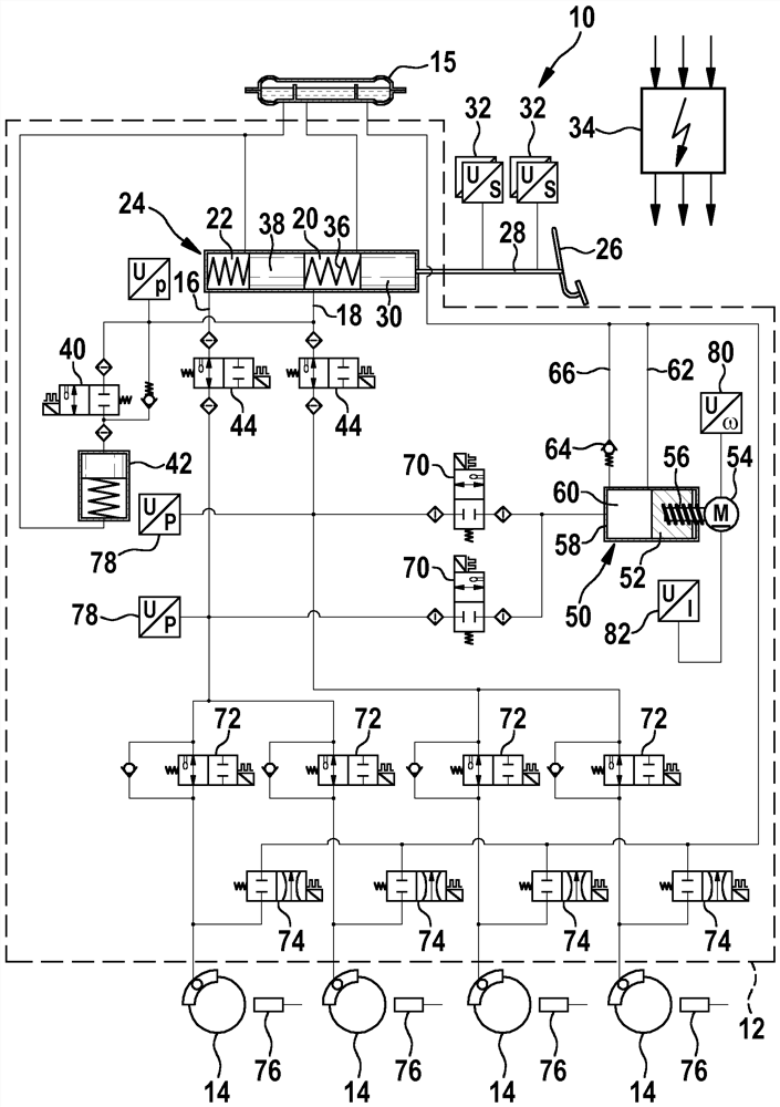
[0011] As already mentioned above, FIG. 1 shows a hydraulic circuit diagram of a first brake device 10 on which the invention is based as an example of an electronically slip-adjustable brake system.

[0012] Brake systems which can be adjusted electronically are known per se from DE 10 2014 222 759 A1.

[0013] The brake device 10 shown is subdivided into a hydraulic unit 12 , wheel brakes 14 attached thereto, and a likewise attached pressure medium container 15 . A total of four wheel brakes 14 are present, each of which is supplied in pairs with pressure medium via the two existing brake circuits 16 and 18 .

[0014] One of the two brake circuits 16; 18 of the brake device 10 is attached to one of a total of two pressure medium chambers 20; 22 of the main brake cylinder 24, the main brake In the exemplary embodiment, the cylinder is likewise placed in the hydraulic unit 12 by way of example. Each of the pressure medium chambers 20 ; 22 is in turn connected to the pressure...


PUM


Abstract

A brake system has an actuation device (26) for specifying a brake request by the driver and comprises multiple brake devices which can be actuated independently of one another by an electronic controller (34). A first brake device (10) has a wheel brake (14) to which a pressure medium under a braking pressure can be applied by a drivable pressure generator (50), wherein the pressure generator (50) can be brought into contact with a pressure medium reservoir (15) via a supply line (62). A second brake device is equipped with a drivable electric machine in order to convert kinetic energy of the motor vehicle into electric energy. Both brake devices together contribute to the process of generating the braking power of the brake system, wherein the proportion each brake device contributes to the braking power is variable. If the braking power can be raised solely by the second brake device, a connection through which the pressure medium can flow is established between the wheel brake (14) and the pressure medium reservoir (15) by means of the electronic controller (34) in order to reduce a grinding torque potentially present at the wheel brake (14) of the first brake device (10).

Description

technical field [0001] The invention relates to a method for controlling an electronically slip-adjustable brake system for a motor vehicle according to the features of the preamble of claim 1 . Background technique [0002] Known electronically adjustable brake systems of motor vehicles have an actuating device by means of which a brake request can be specified by the driver of the motor vehicle. This braking request is detected by means of a sensor system and supplied to the electronic controller, which ascertains from these input signals the braking power that can be applied by the braking system. This braking power is then jointly applied by a plurality of braking devices which can be actuated or actuated separately from one another by the electronic controller. The first brake device is equipped with a drivable pressure generator, which supplies pressure medium to the wheel brakes under the build-up of the brake pressure, while the second brake device has a drivable el...

Claims


Application Information

Patent Timeline
Patent Type & Authority Applications(China)
IPC IPC(8): B60T8/40B60T13/66B60T13/68B60T13/74
CPCB60T8/4081B60T2270/604B60T13/745B60T13/662B60T13/686B60T13/74B60T13/66B60T8/17B60T13/68B60T8/40B60T7/042B60T13/146B60Y2400/81B60T8/171B60T8/4077
Inventor J·瓦纳D·弗兰克C·M·普雷托里乌斯
Owner ROBERT BOSCH GMBH
Why Eureka
Try Eureka