
Vehicle and front and rear wheel braking force distribution system thereof

A technology of braking force distribution and front and rear wheels, which is applied in the field of vehicle engineering, and can solve problems such as affecting vehicle braking stability, large braking control force, and rear wheel slippage

Active Publication Date: 2018-11-27
HANGCHA GRP
View PDF8 Cites 3 Cited by
  • Summary
  • Abstract
  • Description
  • Claims
  • Application Information

AI Technical Summary

Problems solved by technology

[0007] However, the following problems still exist in the partial pressure dual-pipeline system: the pressure ratio of the proportional valve is fixed, and only static proportional control can be realized. Factors such as the change of front and rear axle loads under full load and full load traction, that is, the load transfer between the front and rear axles, are difficult to satisfy
In actual engineering use, the rear axle often has insufficient braking and excessive braking. For the former, the adhesion of the axle load is underutilized, and the braking force is smaller than the adhesion of the wheel, resulting in long braking distance and large braking control force; Or, the braking force is greater than the adhesion of the wheels. When the braking force is large, the load on the rear axle decreases due to factors such as the load transfer of the front and rear axles, that is, the adhesion of the wheels on the rear axle decreases. When the braking force remains unchanged, The rear wheels will slip and form drag marks, seriously affecting the braking stability of the vehicle (vehicle deviation, tail flicking), causing safety hazards. At the same time, because the sliding friction coefficient of the wheel is smaller than the rolling friction coefficient, slipping will cause the braking distance to be longer , the wheel is severely worn and has a short service life

Method used

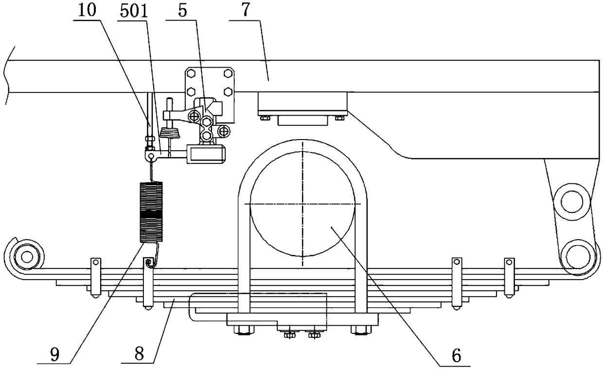
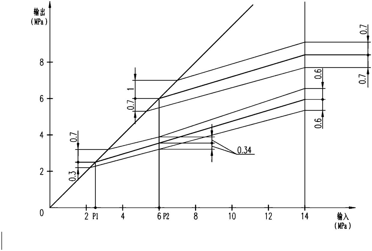

Image

  • Vehicle and front and rear wheel braking force distribution system thereof
  • Vehicle and front and rear wheel braking force distribution system thereof
  • Vehicle and front and rear wheel braking force distribution system thereof

Examples


Embodiment Construction

[0025] The following will clearly and completely describe the technical solutions in the embodiments of the present invention with reference to the accompanying drawings in the embodiments of the present invention. Obviously, the described embodiments are only some, not all, embodiments of the present invention. Based on the embodiments of the present invention, all other embodiments obtained by persons of ordinary skill in the art without making creative efforts belong to the protection scope of the present invention.

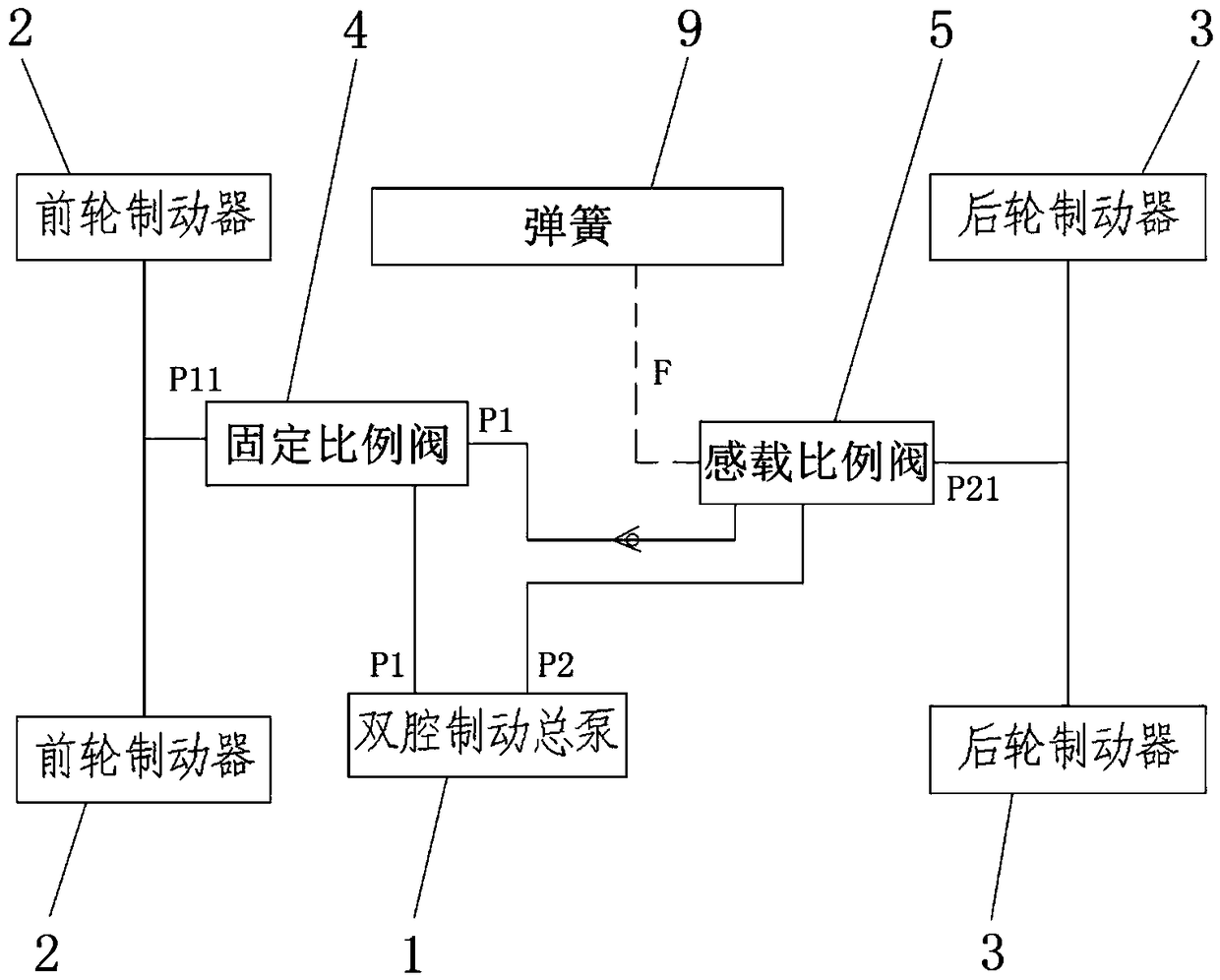
[0026] Please refer to figure 1 , figure 1 It is a schematic diagram of the system hydraulic pipeline connection structure in a specific embodiment provided by the present invention.

[0027] In a specific embodiment provided by the present invention, the front and rear wheel braking force distribution system of the vehicle mainly includes a dual-chamber brake master cylinder 1, a front wheel brake 2, a rear wheel brake 3, a fixed proportional valve 4 and a l...


PUM


Abstract

The invention discloses a front and rear wheel braking force distribution system of a vehicle. The system comprises a double-cavity brake master pump, a front wheel brake, a rear wheel brake, a fixedproportion valve and a load sensing proportion valve, the double-cavity brake master pump is used for providing brake pressure, the front wheel brake and the rear wheel brake are communicated with twoindependent oil outlets on the double-cavity brake master pump, the fixed proportion valve is communicated between the front wheel brake and one oil outlet of the double-cavity brake master pump, theload sensing proportion valve is communicated between the rear wheel brake and the other oil outlet of the double-cavity brake master pump and used for controlling the output pressure of the double-cavity brake master pump for the rear wheel brake according to the corresponding relationship between preset rear axle load variation and ideal rear axle braking force. According to the system, the braking force of a rear axle can be reasonably distributed according to load variation of a front axle and the rear axle, so that the rear axle has suitable braking force, insufficient or excessive braking of the rear axle is avoided, and braking stability and braking reliability of the vehicle are improved. The invention further discloses a vehicle which has the advantages.

Description

technical field [0001] The invention relates to the technical field of vehicle engineering, in particular to a braking force distribution system for front and rear wheels of a vehicle. The present invention also relates to a vehicle comprising the above-mentioned front and rear wheel braking force distribution system. Background technique [0002] With the development of China's machinery industry, more and more machinery and equipment have been widely used. [0003] In the field of industrial vehicles, different types of vehicles have been put into production and use. Among them, logistics equipment vehicles are mainly divided into forklifts, storage vehicles and tractors. Taking the tractor as an example, the tractor works by connecting the tractor to the trailer group through a hook. It is often used for medium and long-distance point-to-point transportation, such as the transportation from the warehouse of the automobile manufacturing industry to the assembly line, and...

Claims


Application Information

Patent Timeline
IPC IPC(8): B60T8/00B60T13/122
CPCB60T8/00B60T13/141
Inventor 关炜余云鹏谢国生吴清波
Owner HANGCHA GRP
Learn More