Intelligent injection mold facilitating sprue stripping
A technology of injection mold and injection mold, which is applied in the field of molds, can solve problems such as increased difficulty in shedding, impact on injection molding quality, unfavorable injection molding, etc., and achieves the effects of improving injection molding quality, ensuring smoothness, and avoiding leakage
- Summary
- Abstract
- Description
- Claims
- Application Information
AI Technical Summary
Problems solved by technology
Method used
Image
Examples
Embodiment 1
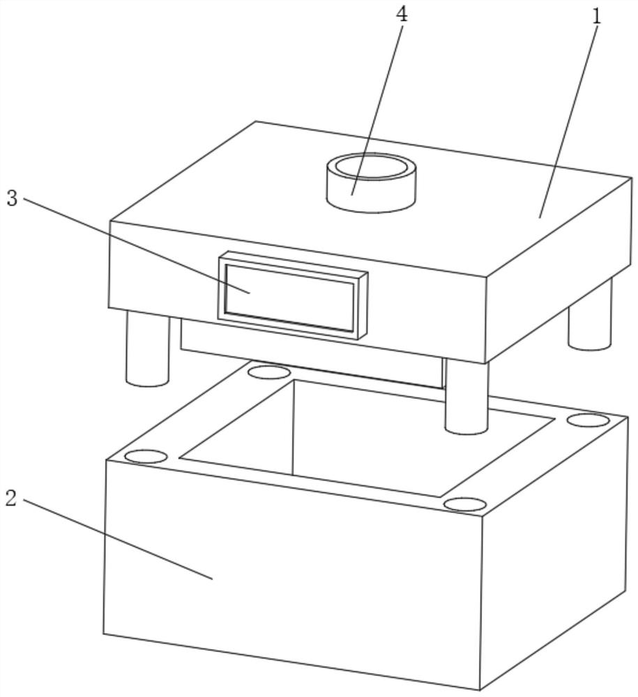
[0036] Such as Figure 1-4 As shown, the present invention provides a technical solution: an intelligent injection mold that is convenient for gate stripping, including an upper injection mold 1 and a lower template 2, and an intelligent temperature display 3 is fixedly connected to the middle position of the outer front of the upper injection mold 1, A pouring part 4 is provided at the middle position of the outer top of the upper injection mold 1;
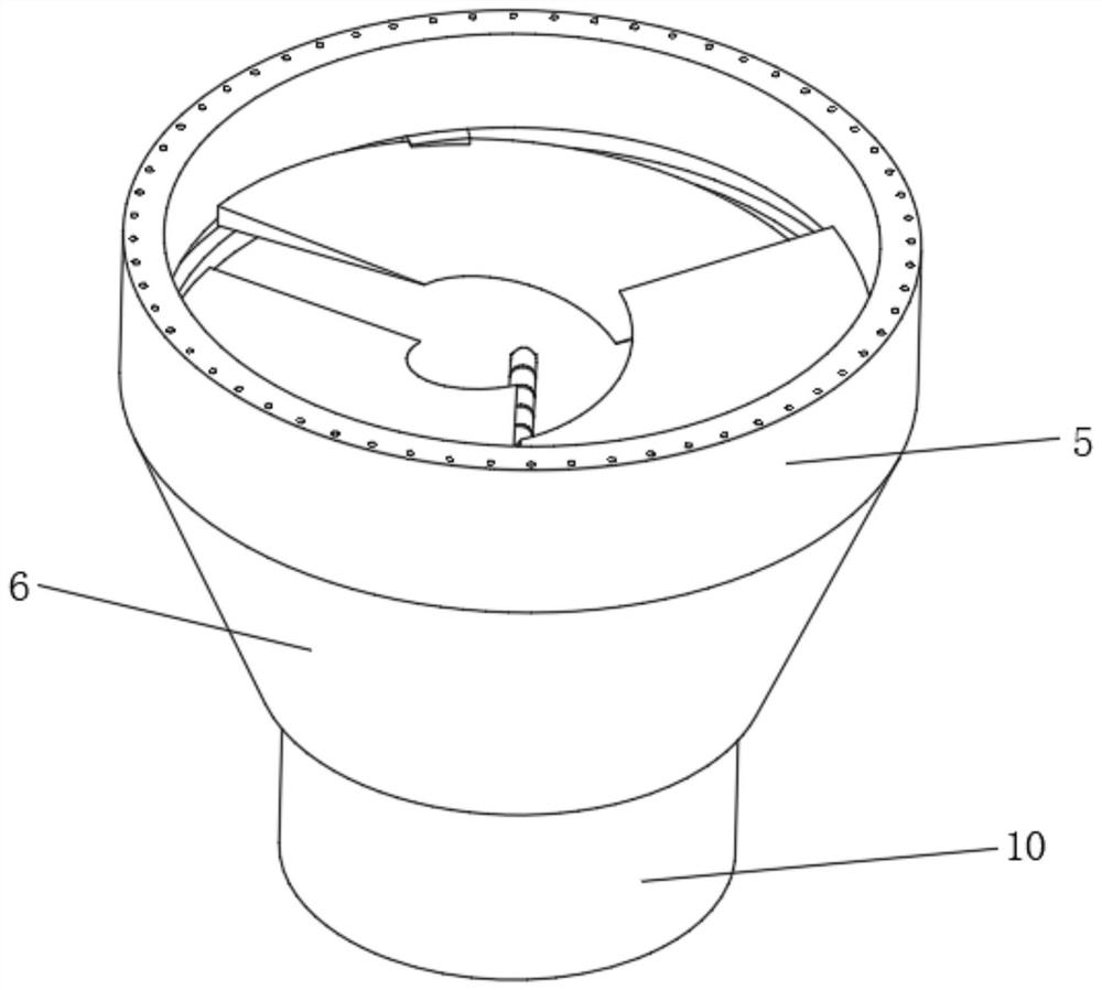
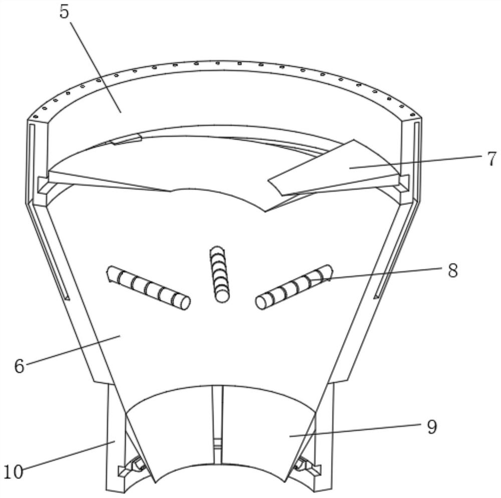
[0037] The pouring part 4 includes a docking groove 5, and the bottom end of the docking groove 5 is fixedly connected with a displacement cone groove 6, and a feeding groove 10 is arranged under the docking groove 5, and a pouring and stirring mechanism 7 is arranged at the middle position inside the docking groove 5, and the feeding An air separation mechanism 8 is provided in the middle of the tank 10 , and a gate deformation mechanism 9 is fixedly connected to the inner side of the pouring and stirring mechanism 7 .
[0038]...
Embodiment 2
[0040] Such as Figure 5-6 As shown, on the basis of Embodiment 1, the present invention provides a technical solution: an intelligent injection mold that facilitates gate stripping. The air separation mechanism 8 includes an air-guiding inner groove 81, which is arranged Above the inside of the tapered groove 6 , and the top of the air guide inner groove 81 extends to the inside of the docking groove 5 , and the surface of the top of the docking groove 5 and corresponding to the air guide inner groove 81 is provided with an external leakage discharge hole 82 .
[0041]The surface inside the displacement cone groove 6 is evenly and fixedly connected with an air separation assembly 83 , and the outer end of the air separation assembly 83 communicates with the inside of the air guide inner groove 81 .
[0042] The air separation assembly 83 includes a negative pressure generating tube 831. The output end of the negative pressure generating tube 831 communicates with the inner ta...
Embodiment 3
[0045] Such as Figure 7-8 As shown, on the basis of Embodiment 1 and Embodiment 2, the present invention provides a technical solution: an intelligent injection mold that facilitates gate stripping. The gate deformation mechanism 9 includes a storage inner groove 91, and the storage inner groove 91 It is arranged at the position close to the bottom inside the feed tank 10, and the position close to the top inside the feed tank 10 is fixedly connected with an elastic separator 92, and the inside of the storage inner tank 91 and the position corresponding to the elastic separator 92 are all fixedly connected with stretching Deformation component 93. Cut and separate the material at the gate position to reduce the amount of connection between the gate position material and the molding body.
[0046] The tensile deformation assembly 93 includes an adjustment slideway 931, which is arranged on the top of the storage inner tank 91. The bottom of the adjustment slideway 931 is slid...
PUM
 Abstract
Description
Claims
Application Information
 - R&D
- Intellectual Property
- Life Sciences
- Materials
- Tech Scout
- Unparalleled Data Quality
- Higher Quality Content
- 60% Fewer Hallucinations
Browse by: Latest US Patents, China's latest patents, Technical Efficacy Thesaurus, Application Domain, Technology Topic, Popular Technical Reports.
© 2025 PatSnap. All rights reserved.Legal|Privacy policy|Modern Slavery Act Transparency Statement|Sitemap|About US| Contact US: help@patsnap.com


