Aero-engine blade spraying production line and control method

A technology of aero-engine and production line, applied in coating, spray booth, spray device, etc., to achieve the effect of efficient spraying operation, improving spraying drying efficiency, and reliable lifting

Pending Publication Date: 2021-07-23
安徽圭目机器人有限公司
View PDF0 Cites 0 Cited by
  • Summary
  • Abstract
  • Description
  • Claims
  • Application Information

AI Technical Summary

Problems solved by technology

For this reason, the applicant proposed a spraying and drying production line for aeroengine blades, which includes a spraying part and a drying part. At present, there is no matching and efficient aeroengine blade spraying production line on the market.

Method used


Image

  • Aero-engine blade spraying production line and control method
  • Aero-engine blade spraying production line and control method
  • Aero-engine blade spraying production line and control method

Examples


Embodiment

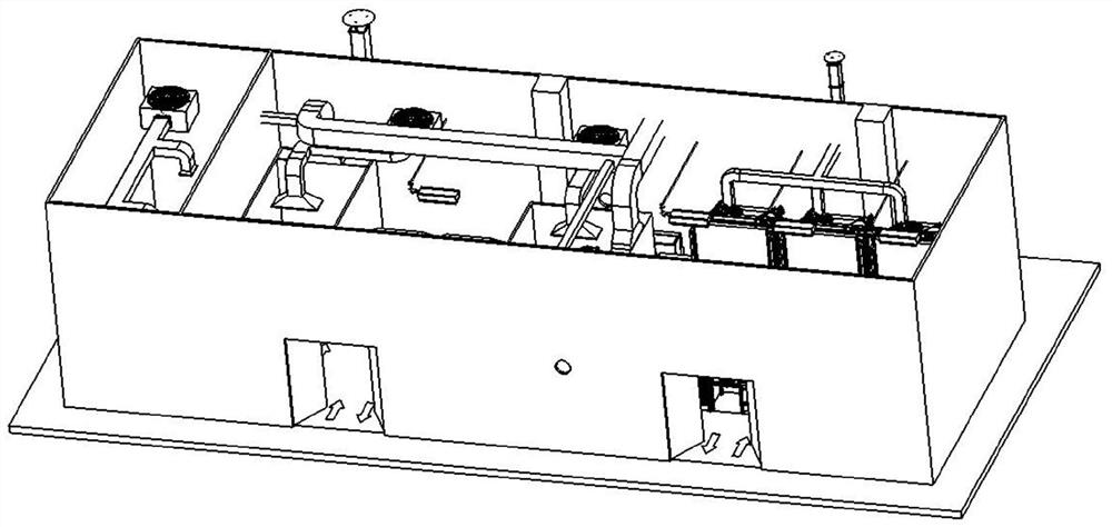
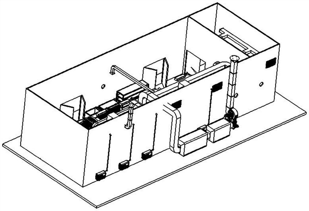
[0050] like Figure 1 to 18 As shown, the present embodiment provides an air engine blade spray drying production line for surface spraying of the blade 8 of the aviation engine. It should be noted that the "first", "second" sequence term used in the present embodiment is only used to distinguish the same type of component, and cannot understand a particular limitation of the scope of protection. Further, as described in the "bottom", "top", "four-week edge", "center", "" bottom "," center ", and" center "," in the present embodiment.

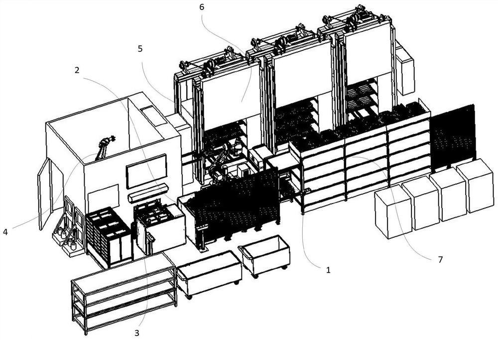
[0051] like Figure 1 to 5 As shown, the air engine blade spray drying production line of the present embodiment is placed in the processing production chamber, and a ventilation purification system is provided at the top of the processed production chamber. Among them, the air engine blade spray drying production line mainly includes blade material plate upper tip 1, first blade material disk transport mechanism 2, second blade material disk transpo...


PUM


Abstract

The invention discloses an aero-engine blade spraying production line which comprises a blade tray feeding opening, a first blade tray conveying mechanism, a second blade tray conveying mechanism, a spraying mechanism, a storage frame parallel to the first blade tray conveying mechanism, a blade drying mechanism and a blade tray batching robot, wherein the first blade tray conveying mechanism, the second blade tray conveying mechanism and the spraying mechanism are arranged in the direction of the production line; and the blade drying mechanism is arranged opposite to the storage frame, and the blade tray batching robot is arranged parallel to the blade tray feeding port and the first blade tray conveying mechanism and used for forking blade trays on the blade tray feeding port and placing the blade trays on the first blade tray conveying mechanism. By means of the scheme, the aero-engine blade spraying production line has the advantages of being simple in structure, small in occupied area, reliable in action, efficient in machining and the like, and has very high practical value and popularization value in the technical field of aero-engine blade spraying.

Description

Technical field [0001] The present invention relates to the field of aero-engine blade spraying techniques, in particular a aeronautical blade spray production line and a control method. Background technique [0002] With the continuous development of aerospace engine and gas turbine, its working temperature is also gradually increased, and the working environment will be equal. At present, the exit temperature of the compressor segment of the advanced engine in the prior art has exceeded 650 ° C, while the combustion chamber temperature can be proximate 2000 ° C, and the high pressure turbine inlet temperature can reach 1650-1750 ° C. However, the prior art can afford the temperature of the material to be limited, and the properties of the matrix heat resistance and oxidation resistance in the high temperature environment will also be reduced. The erosion of the marine environment and dust environment on the "two machines" is greatly caused to reduce the life of the engine blade...

Claims


Application Information

Patent Timeline
IPC IPC(8): B05B16/20B05B13/02B05B13/04B05D3/02B05B16/40
CPCB05B16/20B05B13/0221B05B13/0431B05D3/0254B05B16/40
Inventor 胥健凌正刚周庆陈茂林桂仲成
Owner 安徽圭目机器人有限公司
Why Eureka
Try Eureka