Rotary filter screen manual turning gear

A manual cranking and rotating filter technology is applied in the field of nuclear power plant maintenance, which can solve problems such as hidden safety hazards, the separation of the crank handle and the motor shaft to hurt people or equipment, and the damage to the rotating filter.

Pending Publication Date: 2021-07-23
JIANGSU NUCLEAR POWER CORP
View PDF0 Cites 0 Cited by
  • Summary
  • Abstract
  • Description
  • Claims
  • Application Information

AI Technical Summary

Problems solved by technology

[0008] However, there are the following problems or hidden dangers in the use of the above-mentioned traditional turning handwheel: 1. When the load water level difference of the rotating filter screen is greater than 500 mm, the deflection of the stressed member of the rotating filter screen frame has exceeded the design allowable deflection of the stressed member of the rotating filter screen frame ≤ 1 / 500, at this time, using the traditional turning handwheel to forcibly turn the rotating filter manually will easily damage the mechanical parts of the rotating filter, and even cause greater damage to the rotating filter; 2. When the operator uses the traditional turning handwheel, the turning direction It should be the normal running direction of the rotating filter. The traditional handle does not have any measures to prevent the turning of the turning handle. During the turning process, if the operator accidentally releases the turning handle, the turning handle will quickly turn in the opposite direction. Rotate, at this time it is very easy to make the turning handle and the motor shaft fly away and hurt people or equipment, and the subsequent turning work must start from scratch
[0009] In order to solve the existing problems and potential safety hazards of the existing traditional turning handwheel, improve the safety of operators who manually turn and start the rotating filter, and reduce the risk of injury to operators and surrounding equipment, it is urgent to develop a safer and more reliable rotating filter. Filter manual turning device

Method used


Image

  • Rotary filter screen manual turning gear
  • Rotary filter screen manual turning gear
  • Rotary filter screen manual turning gear

Examples


Embodiment Construction

[0034] The present invention will be described in further detail below in conjunction with the accompanying drawings and embodiments.

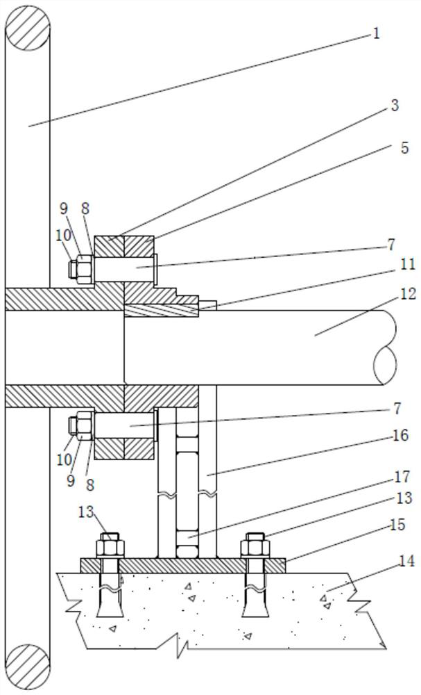
[0035] Such as figure 1 As shown, it is a traditional turning handwheel in the prior art. A keyway is provided at the edge of the center hole of the turning handwheel. The keyway corresponds to the keyway on the motor shaft. Through the keyway on the turning handwheel and the motor shaft The key that matches the keyway on the top is fixedly connected to the turning hand wheel on the motor shaft.

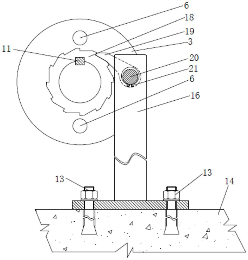
[0036] Such as Figure 2-4As shown, a manual turning device for a rotary filter screen provided by the present invention includes: a turning hand wheel 1, a first flange 3, a second flange 5, a pin 7, a nut 9, a key 11, an expansion bolt 13, a ground Foot steel plate 15, ratchet support 16, ratchet 18, ratchet 19, fixed pin 20 and jump ring 21.

[0037] Such as figure 2 As shown, the first flange 3 is fixedly connected to the center of the turni...


PUM


Abstract

The invention belongs to the field of nuclear power station maintenance, and particularly relates to a rotary filter screen manual turning gear which comprises a turning hand wheel, a first flange, a second flange, a pin, a nut, a key, a pawl support, a ratchet wheel, a pawl, a fixing pin and a clamping spring. The first flange is fixedly connected to the central position of the turning hand wheel; the second flange is fixedly connected with a motor shaft through the key; the first flange and the second flange are fixedly connected through matching of the pin and the nut; the ratchet wheel is fixedly connected to a center hole of the second flange and forms an integrally-formed structure with the second flange. The pawl support is fixedly connected to the concrete ground, the pawl is fixedly connected to the upper portion of the pawl support through cooperation of the fixing pin and the clamping spring, and the pawl is meshed with the ratchet wheel. Torque transmission and overload protection on the rotary filter screen during manual turning are achieved, the situation that a turning hand wheel rotates to drive a motor to rotate in the manual turning process is effectively prevented, and meanwhile the safety of operators and peripheral equipment is guaranteed.

Description

technical field [0001] The invention belongs to the field of maintenance of nuclear power plants, and in particular relates to a manual turning device for a rotating filter screen. Background technique [0002] The main system function of the circulating cooling water system of Tianwan Nuclear Power Plant (referred to as PA system) is to provide cooling water to the condenser and auxiliary cooler of the conventional island, and it is the cold end system for the operation of the power plant. Transport the heat load collected by the equipment cooling water system to the final heat sink—sea water, and provide the nuclear island with cooling water for the safety plant water system under normal operation, cold shutdown and accident shutdown conditions, so as to facilitate safety-related structures Transfer heat from internal systems and components to final heat sinks. The circulating cooling water system of a single unit is divided into four independent channels in front of the ...

Claims


Application Information

Patent Timeline
IPC IPC(8): B01D29/96B01D35/00
CPCB01D29/96B01D35/00
Inventor 张军超曾振华曹晔刘勇尤晓波易良川隋震赵翔张建军
Owner JIANGSU NUCLEAR POWER CORP
Why Eureka
Try Eureka