
Waste heat recovery device of aluminum alloy smelting furnace

A waste heat recovery device and aluminum alloy technology, which is applied in the field of aluminum alloy melting furnaces, can solve the problems that heat cannot be recycled and utilized

Pending Publication Date: 2021-07-20
宁波卓锋汽车科技有限公司
View PDF0 Cites 0 Cited by
  • Summary
  • Abstract
  • Description
  • Claims
  • Application Information

AI Technical Summary

Problems solved by technology

[0003] This application provides a waste heat recovery device for an aluminum alloy melting furnace, which is used to solve the problem in the prior art that the heat lost in the vortex chamber to the external air cannot be recovered and utilized

Method used


Image

  • Waste heat recovery device of aluminum alloy smelting furnace
  • Waste heat recovery device of aluminum alloy smelting furnace
  • Waste heat recovery device of aluminum alloy smelting furnace

Examples


Embodiment Construction

[0028] The implementation manner of the present application will be further described in detail below with reference to the drawings and embodiments. The following examples are used to illustrate the present application, but cannot be used to limit the scope of the present application.

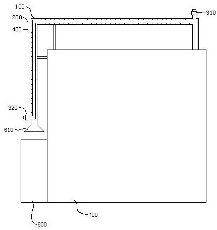
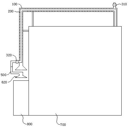
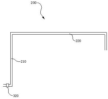
[0029] Such as figure 1 As shown, in the embodiment of the present application, an aluminum alloy melting furnace waste heat recovery device is provided, including a tail gas collection pipe 100 and a heat exchange pipe 200, the inlet of the tail gas collection pipe 100 is located above the opening of the swirl chamber 800, and the tail gas is The tube 100 is sleeved on the outside of the heat exchange tube 200, one end of the heat exchange tube 200 extends to the inlet of the exhaust gas collection tube 100 and is located outside the exhaust gas collection tube 100, and the other end of the heat exchange tube 200 communicates with the interior of the furnace body 700 ; The exhaust gas collec...


PUM


Abstract

The invention provides a waste heat recovery device of an aluminum alloy smelting furnace. The waste heat recovery device comprises a tail gas collecting tube and a heat exchange tube, wherein an air inlet of the tail gas collecting tuber is located above an opening of a swirl chamber, the tail gas collecting tube is connected to the outer side of the heat exchange tube in a sleeving manner, one end of the heat exchange tube stretches into the air inlet of the tail gas collecting tube and is located outside the tail gas collecting tube, and the other end of the heat exchange tube is communicated with the furnace body internally; the tail gas collecting tube is provided with a first fan, and the heat exchange tube is provided with a second fan; and a guiding vane is arranged between the inner wall of the tail gas collecting tube and the inner wall of the heat exchange tube, and the guiding vane is arranged spirally around a center axis of the heat exchange tube.

Description

technical field [0001] The present application relates to the technical field of aluminum alloy melting furnaces, in particular to a waste heat recovery device for aluminum alloy melting furnaces. Background technique [0002] The aluminum alloy melting furnace is used to heat and melt aluminum alloy raw materials. The aluminum alloy melting furnace in the prior art includes a furnace body and a vortex chamber. Through the vortex chamber, the vortex chamber is located outside the furnace body, and the opening of the vortex chamber faces upward and is open. When the liquid aluminum is in the vortex chamber, the liquid surface is in contact with the external air, and the aluminum chips are put into the vortex chamber. The liquid aluminum in the vortex chamber makes the aluminum The shavings are melted or the aluminum shavings are brought into the furnace body to be melted again. Due to the high temperature of the liquid aluminum, the liquid aluminum transfers heat to the outs...

Claims


Application Information

Patent Timeline
IPC IPC(8): F27D17/00
CPCF27D17/004F27D17/001Y02P10/25
Inventor 李伟锋潘美妙李迎朝王胡冉王双飞
Owner 宁波卓锋汽车科技有限公司
Learn More