
Heat treatment device for mechanical arm rotating shaft machining

A technology of heat treatment devices and manipulators, applied in heat treatment furnaces, heat treatment equipment, quenching devices, etc., can solve the problems of increased consumption costs, complex structures, and increased costs, and achieve the effects of simple structure, complex structures, and uniform heat treatment

Inactive Publication Date: 2022-02-01
太仓博超精密机械设备有限公司
View PDF0 Cites 0 Cited by
  • Summary
  • Abstract
  • Description
  • Claims
  • Application Information

AI Technical Summary

Problems solved by technology

[0004] In order to solve the problem that most of the above-mentioned existing heat treatment devices for manipulator shaft processing are complex in structure, so the production cost of the equipment is increased, and the cooling liquid in the use process cannot be recycled, and the problem of cost consumption during heat treatment is increased. The purpose is to provide a heat treatment device for manipulator shaft processing

Method used


Image

  • Heat treatment device for mechanical arm rotating shaft machining
  • Heat treatment device for mechanical arm rotating shaft machining
  • Heat treatment device for mechanical arm rotating shaft machining

Examples


Embodiment Construction

[0020] In order to explain the overall concept of the present invention more clearly, the following will be described in detail by way of examples in conjunction with the accompanying drawings.

[0021] In describing the present invention, it is to be understood that the terms "center", "upper", "lower", "front", "rear", "left", "right", "vertical", "horizontal", The orientation or positional relationship indicated by "top", "bottom", "inner", "outer", "axial", "radial" and "circumferential" are based on the orientation or positional relationship shown in the drawings, only It is for the convenience of describing the present invention and simplifying the description, but does not indicate or imply that the referred device or element must have a specific orientation, be constructed and operated in a specific orientation, and thus should not be construed as limiting the present invention.

[0022] In addition, the terms "first" and "second" are used for descriptive purposes only...


PUM


Abstract

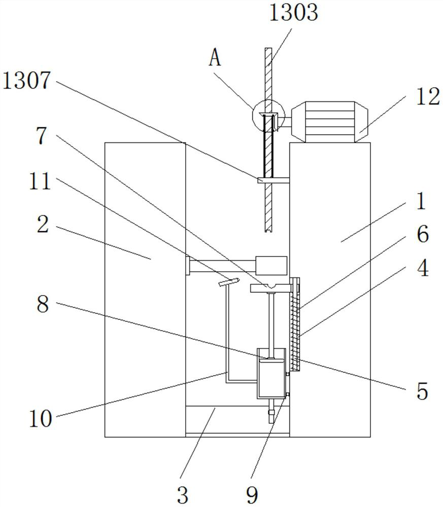
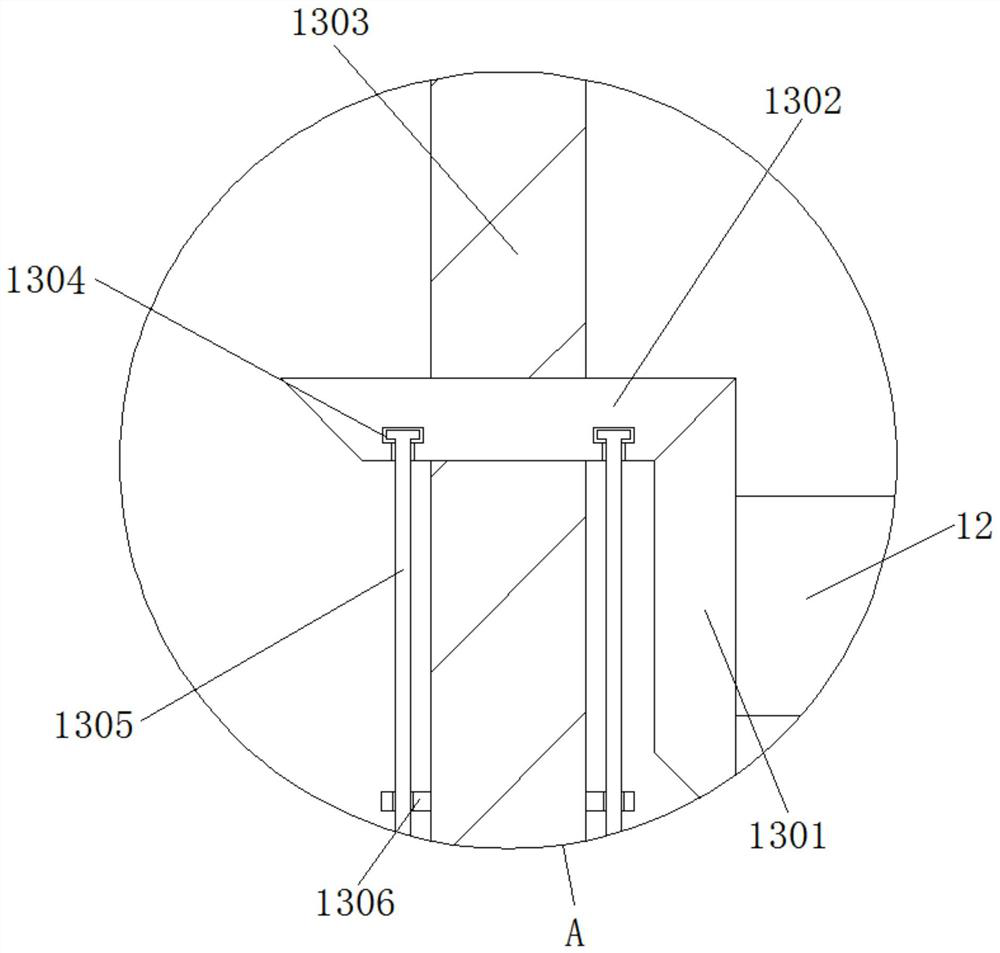
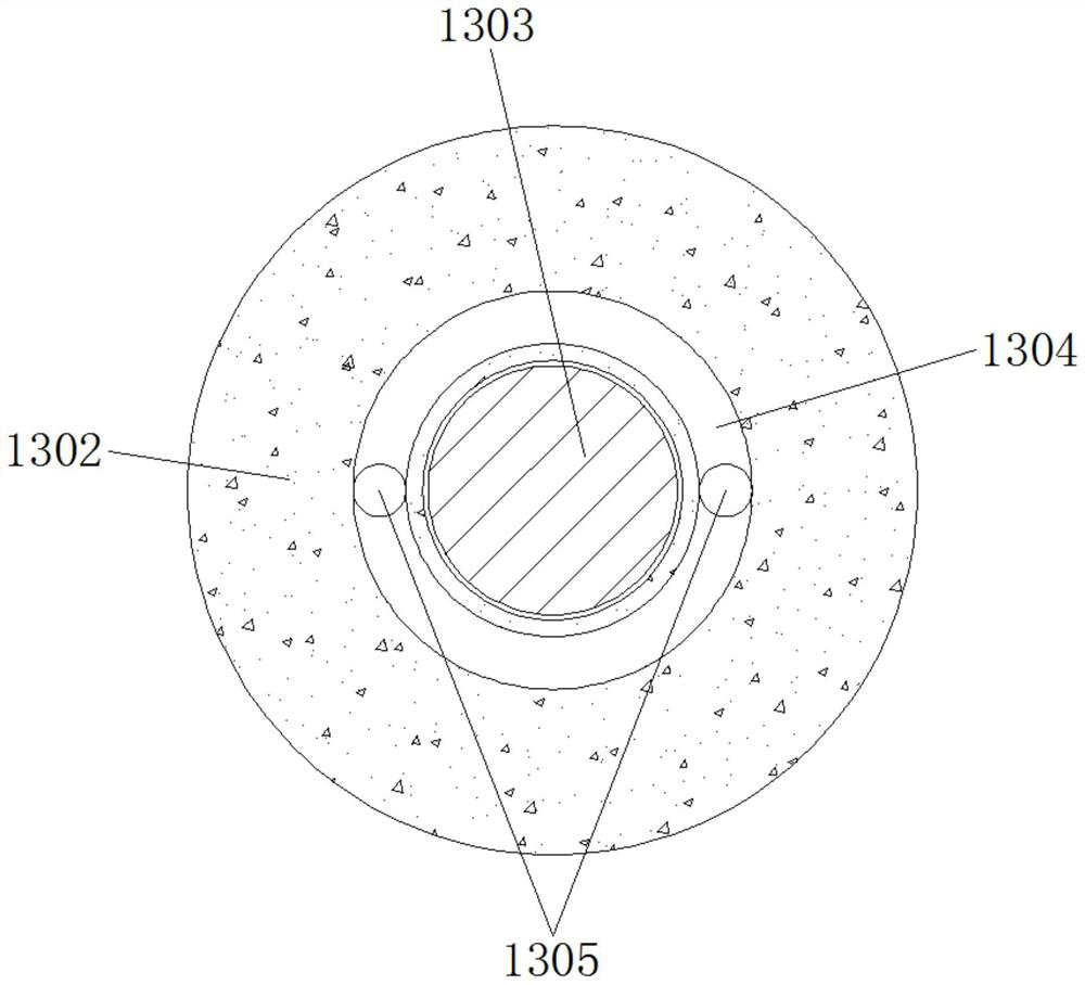
The invention discloses a heat treatment device for mechanical arm rotating shaft machining which comprises a machine body and induction heat treatment equipment, a water storage tank is arranged between the machine body and the induction heat treatment equipment, a sliding groove is formed in the side wall of the machine body, a sliding rod is arranged in the sliding groove, and a spring is arranged on the surface of the sliding rod; a sliding block is arranged on the surface of the sliding rod, and one end of the spring is fixedly connected with the sliding block. According to the heat treatment device for mechanical arm rotating shaft machining, through mutual cooperation of a piston, a water storage pipe, a water conveying pipe, a spray head and other parts, when the piston moves downwards along with a sliding block, water flow in the water storage pipe can be conveyed to the spray head through an output pipe to complete heat treatment; and meanwhile, when the sliding block drives the piston to ascend, the water suction pipe below the water storage pipe can suck cooling liquid which completes quenching and gathers in the water storage tank into the water storage pipe again, secondary quenching is completed, and the problem that cooling liquid of existing equipment cannot be recycled is solved.

Description

technical field [0001] The invention belongs to the technical field of manipulator processing, and in particular relates to a heat treatment device for manipulator shaft processing. Background technique [0002] A complete manipulator is composed of multiple parts. The joints of these parts need to be connected by the rotating shaft. In order to make the physical properties of the rotating shaft itself, such as hardness and temperature resistance, meet the connection requirements, it is necessary to carry out special inspections during the production of the rotating shaft. Heat treatment operation, and the most commonly used heat treatment method for existing shafts is induction heat treatment. [0003] It should be noted that most of the existing heat treatment devices for manipulator shaft processing are complex in structure, so the production cost of the equipment is increased, and the cooling liquid in the use process cannot be recycled, and the consumption cost of heat ...

Claims


Application Information

Patent Timeline
IPC IPC(8): C21D1/667C21D1/10C21D9/28
CPCC21D1/667C21D1/10C21D9/28Y02P10/20Y02P10/25
Inventor 谭元金
Owner 太仓博超精密机械设备有限公司
Learn More