Organic pollutant anodic oxidation treatment device based on proton exchange membrane

A technology of proton exchange membrane and anodic oxidation, which is applied in the direction of water pollutants, water/sewage treatment, water/sludge/sewage treatment, etc. It can solve the problems of difficult electrolyte recovery, low electrode current density, frequent maintenance, etc., and achieve no Risk of corrosion and leakage, low ion conduction resistance, and no secondary pollution

Pending Publication Date: 2021-07-20
MATERIAL INST OF CHINA ACADEMY OF ENG PHYSICS
View PDF20 Cites 0 Cited by
  • Summary
  • Abstract
  • Description
  • Claims
  • Application Information

AI Technical Summary

Problems solved by technology

[0004] 1) Low current density, high energy consumption, and slow processing speed per unit area
The electrolytic water device based on traditional separated electrodes has a large distance between cathode and anode plates, the electrodes are connected by electrolyte solution, the internal resistance is large, and the electrode current density is low (generally no more than 50mA / cm 2 ), high working voltage and high power consumption; low current density results in slow processing speed of organic matter per positive plate per unit area, in order to speed up the processing speed, the scale of the electrolytic cell can only be expanded, which will further increase energy consumption
[0005] 2) Many processing steps, low efficiency, easy to produce secondary pollution
The added corrosive acid or salt electrolyte is not easy to recycle, and is generally discharged as waste, causing secondary pollution
[0006] 3) The life of the electrolytic cell is short and requires frequent maintenance
Because the electrolyte itself has corrosion damage to the structure of the electrolytic cell, in order to prevent risks such as electrolyte leakage or electrode short circuit caused by corrosion, the traditional electrolytic cell needs to be shut down for maintenance regularly

Method used


Image

  • Organic pollutant anodic oxidation treatment device based on proton exchange membrane
  • Organic pollutant anodic oxidation treatment device based on proton exchange membrane
  • Organic pollutant anodic oxidation treatment device based on proton exchange membrane

Examples


Embodiment 1

[0058] Embodiment 1: (preparation of anode catalyst)

[0059] A method for preparing an anode catalyst, comprising the steps of:

[0060] 1) A certain amount of SnCl 2 .2H 2 O and SbCl 3 Dissolve in water and ethanol mixed solution (alcohol accounts for 80%), the total concentration is 0.05mol / L, SnCl 2 .2H 2 O and SbCl 3 The molar ratio of the solution is 9:1, and the total volume of the solution is 1L.

[0061] 2) Prepare a saturated solution of NaOH with a mixed solution of water and ethanol (absolute ethanol accounts for 80%).

[0062] 3) Titrate 30 mL of the saturated solution prepared in step 2 into the SnCl prepared in step 1 while stirring 2 .2H 2 O and SbCl 3 solution and keep stirring for a while.

[0063] 4) Heat the solution prepared in step 3) to 120° C. and keep it warm for 24 hours.

[0064] 5) The reaction mixture obtained in step 4) is separated and cleaned by centrifugation and suction filtration to obtain the anode catalyst.

Embodiment 2

[0065] Embodiment 2 (preparation of anode catalyst)

[0066] A method for preparing an anode catalyst, comprising the steps of:

[0067] 1) A certain amount of SnCl 2 .2H 2 O and SbCl 3 Dissolved in a mixed solution of water and ethanol (alcohol accounts for 80%), the total concentration is 0.07mol / L, SnCl 2 .2H 2 O and SbCl 3 The molar ratio of the solution is 19:1, and the total volume of the solution is 1L.

[0068] 2) Prepare a saturated solution of NaOH with a mixed solution of water and ethanol (absolute ethanol accounts for 80%).

[0069] 3) Titrate 45mL of the saturated solution prepared in step 2) into the SnCl prepared in step 1 while stirring 2 .2H 2 O and SbCl 3 solution and keep stirring for a while.

[0070] 4) The solution prepared in step 3) was heated to 200° C. and kept for 6 hours.

[0071] 5) The reaction mixture obtained in step 4) is separated and cleaned by centrifugation and suction filtration to obtain the anode catalyst.

Embodiment 3

[0072] Embodiment 3 (preparation of anode catalyst)

[0073] A method for preparing an anode catalyst, comprising the steps of:

[0074] 1) A certain amount of SnCl 2 .2H 2 O and SbCl 3 Dissolve in pure isopropanol to make a solution, the total concentration is 0.1mol / L, SnCl 2 .2H 2 O and SbCl 3 The molar ratio of the solution is 39:1, and the total volume of the solution is 1L.

[0075] 2) Prepare a saturated solution of NaOH with absolute ethanol.

[0076] 3) Titrate 60 mL of the saturated solution prepared in step 2) into the SnCl prepared in step 1 while stirring 2 .2H 2 O and SbCl 3 solution and keep stirring for a while.

[0077] 4) Heat the solution prepared in step 3) to 180° C. and keep it warm for 12 hours.

[0078] 5) The reaction mixture obtained in step 4) is separated and cleaned by centrifugation and suction filtration to obtain the anode catalyst.


PUM

PropertyMeasurementUnit
concentrationaaaaaaaaaa

Abstract

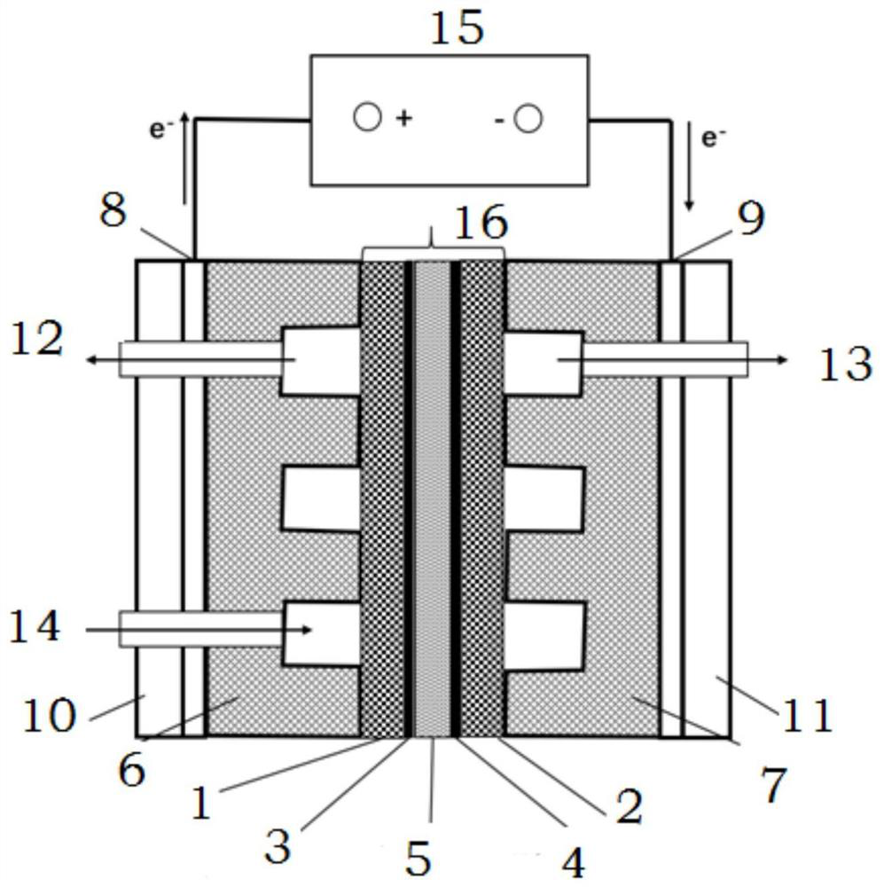
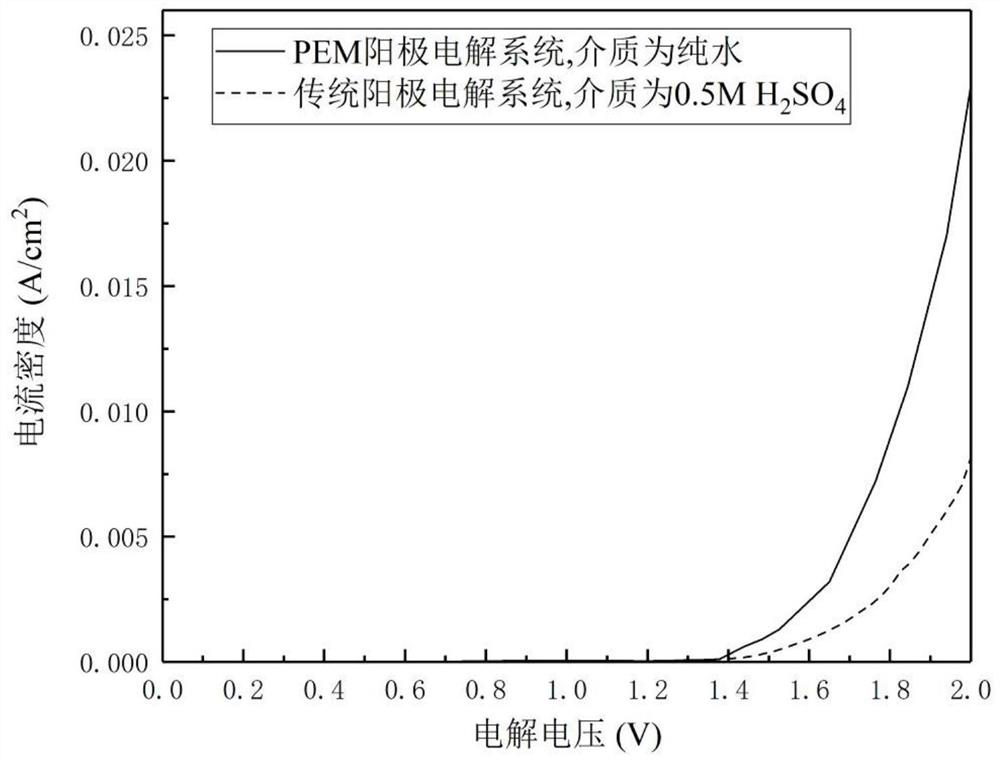
The invention relates to an organic pollutant anodic oxidation treatment device based on a proton exchange membrane. The device comprises a power supply and an electrolytic bath which are electrically connected, a membrane electrode assembly is arranged in the electrolytic bath, and the membrane electrode assembly divides the electrolytic bath into a positive electrode area electrically connected with a positive electrode of the power supply and a negative electrode area electrically connected with a negative electrode of the power supply; and an anode electrode plate and an anode bipolar plate are arranged in the anode region, a cathode electrode plate and a cathode bipolar plate are arranged in the cathode region, and the anode bipolar plate and the cathode bipolar plate are both in contact with the membrane electrode assembly and define a plurality of reaction tanks and the like with the membrane electrode assembly respectively. The device is high in current density, low in energy consumption and high in unit area processing speed. The proton exchange membrane is used as an ion conduction channel, the ion conduction impedance is low, the ion mass transfer speed is high, and the current density is higher than that of traditional anodic oxidation treatment under the same voltage, so that the energy consumption is reduced while the treatment speed is increased.

Description

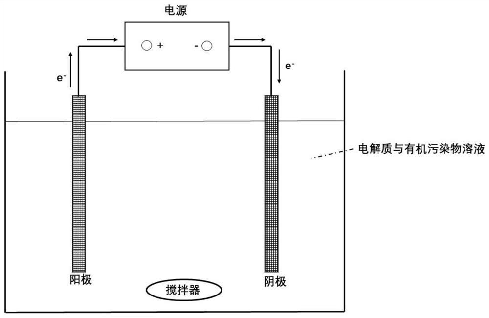
technical field [0001] The invention relates to the technical field of proton exchange membrane electrolysis, in particular to an anodic oxidation treatment device for organic pollutants based on a proton exchange membrane. Background technique [0002] Most of the existing electrochemical oxidation (EO) treatment devices for organic pollutants use the traditional separated electrode electrolysis water mode. A basic organic sewage anodic oxidation treatment device consists of a traditional electrolyzer, a power supply and a stirring device. The traditional electrolytic cell is composed of an anode plate, a negative plate and an electrolytic cell body, and the electrolyte is injected into the electrolytic cell. In order to prevent short circuit, there is a certain gap (1 ~ 10cm) between the cathode and anode plates. SnO loaded on the surface of the anode plate 2 , PbO 2 Or boron doped diamond (Born-doped diamond, BDD), the cathode uses stainless steel sheet or titanium sh...

Claims


Application Information

Patent Timeline
Patent Type & Authority Applications(China)
IPC IPC(8): C02F1/467C02F1/461C02F101/30
CPCC02F1/4672C02F1/46109C02F2101/30
Inventor 孙浩然罗德礼何康昊曾甯蔡金光胡存石岩宋江锋杨莞陈军
Owner MATERIAL INST OF CHINA ACADEMY OF ENG PHYSICS
Why Eureka
Try Eureka