
Air injection auxiliary device of rotor unmanned aerial vehicle

An auxiliary device and unmanned rotor technology, which is applied in the direction of rotorcraft, aircraft indicating devices, unmanned aircraft, etc., can solve the problems of limiting the slope angle of the drone, the inclined center of gravity of the fuselage, and the unbalanced weight of the fuselage. Achieve the effect of avoiding unable to land smoothly, improving response speed, and ensuring safe flight

Pending Publication Date: 2021-07-20
TAIZHOU UNIV
View PDF2 Cites 3 Cited by
  • Summary
  • Abstract
  • Description
  • Claims
  • Application Information

AI Technical Summary

Problems solved by technology

For example, the UAV device disclosed by Patent No. CN109466758B has a spherical anti-drop protection frame, which fully covers the UAV, and cannot be equipped with a camera for aerial photography; The impact device, using the spring as the buffer device
Both of the above two patents use a physical structure to passively avoid obstacles, which cannot solve the problem that the relative speed between the drone and the obstacle is too large when the drone is flying at high speed, and the impact force of the collision is too large. Serious injury, risk of crash
[0004] Existing UAVs all rely on propellers to provide lifting force during the take-off and landing process. General civilian UAVs are equipped with cameras for remote operation, which will cause the weight of the fuselage to be unbalanced.
Problems such as fuselage tilt and center of gravity shift are prone to occur during take-off and landing
During take-off and landing on a slope, if the lift is provided only by the blades, the lift at this time is inclined, and the vertical component is used to overcome the gravity of the drone, while the horizontal component will further accelerate the tilt of the drone’s fuselage and the center of gravity. The development of the offset imbalance direction increases the rollover phenomenon of the UAV, limits the slope angle of the UAV during take-off and landing, and further limits the take-off and landing environment of the UAV.

Method used


Image

  • Air injection auxiliary device of rotor unmanned aerial vehicle
  • Air injection auxiliary device of rotor unmanned aerial vehicle
  • Air injection auxiliary device of rotor unmanned aerial vehicle

Examples


Embodiment Construction

[0048] The specific embodiments of the present invention will be further described below with reference to the accompanying drawings.

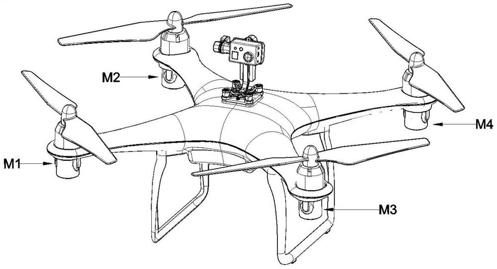
[0049] like figure 1 As shown, a jet auxiliary device of a rotary-wing drone of the present invention includes a drone body, a visual module and a jet auxiliary device. The vision module includes a three-axis gimbal and a camera. The three-axis gimbal consists of three mutually perpendicular pitch axes, roll axes, yaw axes and a base. The base is fixed with the top of the fuselage of the main body of the drone. The roll axis and pitch axis are used to keep the camera in a horizontal position, and the yaw axis realizes the 360° rotation of the camera, so that the orientation of the camera is always consistent with the flight direction of the drone. The camera is installed on the three-axis gimbal directly above the drone, and is connected to the controller with a wire.

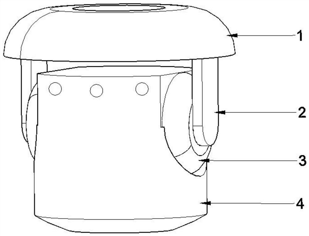
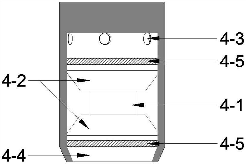
[0050] like figure 2 As shown, the air jet auxiliary device includes ...


PUM


Abstract

The invention discloses an air injection auxiliary device of a rotor unmanned aerial vehicle. The air injection auxiliary device comprises an unmanned aerial vehicle body, a visual module and an air injection auxiliary device body. The visual module comprises a three-axis holder and a camera. The air injection auxiliary device body comprises a base, a rotating shaft, a connecting rod and an air injection device. The air injection device comprises a motor, a fan, an air inlet, an air injection port and a filter screen. The wind resistance of the unmanned aerial vehicle is improved by spraying air towards the same direction of the wind direction through the air spraying auxiliary device. The three-axis holder and the camera are carried, and the air injection mode of the air injection auxiliary device is adopted, so that the active obstacle avoidance capability and the response speed of the unmanned aerial vehicle are improved. The unmanned aerial vehicle can take off and land more simply and stably through different air injection forces of the air injection auxiliary device, and the reliability of the unmanned aerial vehicle is improved. When the unmanned aerial vehicle air injection auxiliary device is in an auxiliary take-off state, all the air injection auxiliary devices inject air vertically and downwards at the same time, and the maximum load of the unmanned aerial vehicle is further improved.

Description

technical field [0001] The patent of the present invention relates to the technical field of the rotary-wing unmanned aerial vehicle, in particular to a jet auxiliary device of the rotary-wing unmanned aerial vehicle. Background technique [0002] At present, most of the UAVs on the market are rotary-wing UAVs, which have poor wind resistance and low load capacity. During the flight of the UAV, the force generated by the wind on the UAV cannot be avoided, and the UAV will tilt to a certain extent under this force; when the flight tilt angle of the multi-rotor aircraft exceeds 30°, the lift of the rotor will drop sharply, which will cause the UAV to tilt. As a result, it will accelerate and fall, and the drone will lose its balance and become difficult to control. When flying at a high altitude, the change in the magnitude and direction of the wind is unpredictable. Conventional UAVs change the direction of the UAV's own lift by changing the pitch and roll angles to combat w...

Claims


Application Information

Patent Timeline
Patent Type & Authority Applications(China)
IPC IPC(8): B64C15/14B64D45/00B64D47/08B64C27/08G05D1/08
CPCB64C15/14B64D45/00B64D47/08B64C27/08G05D1/0816B64U10/10
Inventor 许娟邬玲伟韩光耀蒋招宇林志明郭陈江山
Owner TAIZHOU UNIV
Learn More