Radio frequency power amplifier
A technology of radio frequency power and amplifier, applied in the field of radio frequency power amplifier, can solve the problems of difficulty in manufacturing radio frequency power amplifier and increase in cost of components, and achieve the effect of enhancing the robustness and improving the robustness.
- Summary
- Abstract
- Description
- Claims
- Application Information
AI Technical Summary
Problems solved by technology
Method used
Image

Examples
Embodiment 1
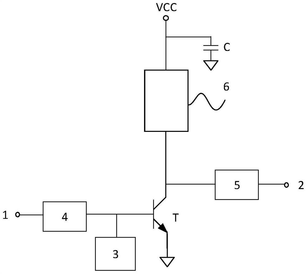
[0037] Such as figure 1 As shown, this embodiment provides a radio frequency power amplifier, including a high-frequency input terminal 1, a high-frequency output terminal 2, a device bias circuit 3, a decoupling capacitor C, a front-end matching circuit 4, an output matching circuit 5 and at least one level amplifier. Wherein, the front-end matching circuit 4 and the output matching circuit 5 are optional items, that is, they may or may not be included, and both are included in this embodiment. The signal of the RF power amplifier enters the front-end matching circuit 4 of the amplifier through the high-frequency input terminal 1, and then outputs to the high-frequency output terminal 2 through the output matching circuit 5 after being amplified by the amplifier. In this embodiment, the amplifier is implemented by a triode T. The device bias circuit 3 is used to bias the input terminal of the amplifier, that is, the base of the triode, and the decoupling capacitor C is conn...
Embodiment 2
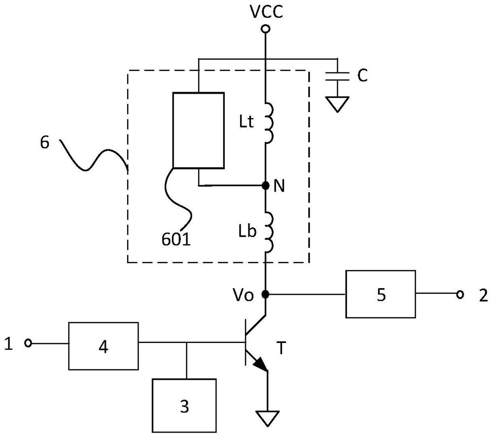
[0042] Such as figure 2 As shown, this embodiment is a further improvement on the basis of Embodiment 1. Wherein, the tolerance circuit 6 includes a clamping circuit 601, a first inductive device Lt and a second inductive device Lb; the first inductive device Lt and the second inductive device Lb are connected in series between the output terminal Vo of the amplifier and the working power supply VCC; An inductive device Lt is connected in parallel with the clamping circuit 601 . One end of the first inductive device Lt is electrically connected to the second inductive device Lb. The other end of the first inductive device Lt is electrically connected to the working power supply VCC.
[0043] In this embodiment, both the first inductive device Lt and the second inductive device Lb can be inductance or a part of the inductance on the chip or chip inductors or chip leads, etc., as long as they are devices with inductance, the present invention is not limited to this .
[004...
Embodiment 3
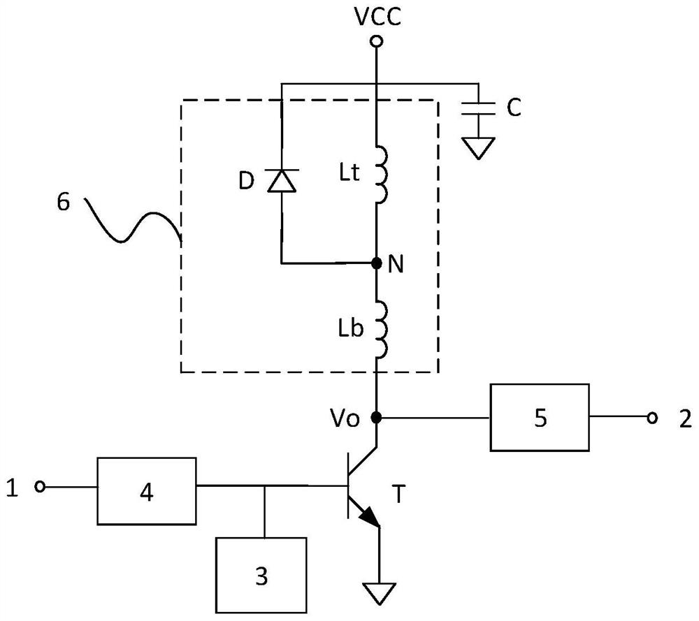
[0046] Such as image 3 As shown, this embodiment is a further improvement on the basis of Embodiment 2. Wherein, the clamping circuit is implemented by a diode D, the anode of the diode D is connected to the working power supply VCC, and the cathode of the diode D is connected to the point N with the second inductive device Lb.
[0047] In this embodiment, in order to reduce the area and cost, an optimal implementation method is adopted, that is, the clamping circuit is implemented with only one diode D. The diode D can also be realized by a triode circuit, specifically, the base and the collector of the triode are short-circuited and used as a diode. Which device to choose to implement the clamping circuit depends on the specific manufacturing process and application requirements, which is not limited in the present invention.
[0048] In this embodiment, no matter how high the voltage or current applied to the radio frequency power amplifier is, limited by the clamping fu...
PUM
 Abstract
Description
Claims
Application Information
 - R&D
- Intellectual Property
- Life Sciences
- Materials
- Tech Scout
- Unparalleled Data Quality
- Higher Quality Content
- 60% Fewer Hallucinations
Browse by: Latest US Patents, China's latest patents, Technical Efficacy Thesaurus, Application Domain, Technology Topic, Popular Technical Reports.
© 2025 PatSnap. All rights reserved.Legal|Privacy policy|Modern Slavery Act Transparency Statement|Sitemap|About US| Contact US: help@patsnap.com