Rotary ultrasonic grinding machine tool and application

A rotary ultrasonic and grinding technology, which is applied to the parts of grinding machine tools, grinding workpiece supports, grinding drive devices, etc. The problem of long route and other problems can reduce grinding burns, improve processing quality and reduce grinding force.

Inactive Publication Date: 2021-07-16
ZHONGBEI UNIV +1
View PDF8 Cites 6 Cited by
  • Summary
  • Abstract
  • Description
  • Claims
  • Application Information

AI Technical Summary

Problems solved by technology

The disadvantage is that the route of the ultrasonic excitation of the grinding wheel is long, and the tool handle and the sleeve are assembled structures, which affect the rigidity and precision of the ultrasonic assisted grinding system
And it can only be used as an accessory of the machine tool spindle to expand the processing capacity of the existing machine tool
It cannot be used as the main shaft of a grinding machine to realize ultrasonic grinding of different surface structures of parts

Method used


Image

  • Rotary ultrasonic grinding machine tool and application
  • Rotary ultrasonic grinding machine tool and application
  • Rotary ultrasonic grinding machine tool and application

Examples


Embodiment Construction

[0042] In order to further illustrate the technical solution of the present invention, the present invention will be further described below through examples.

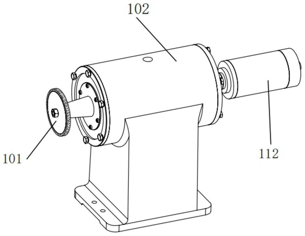
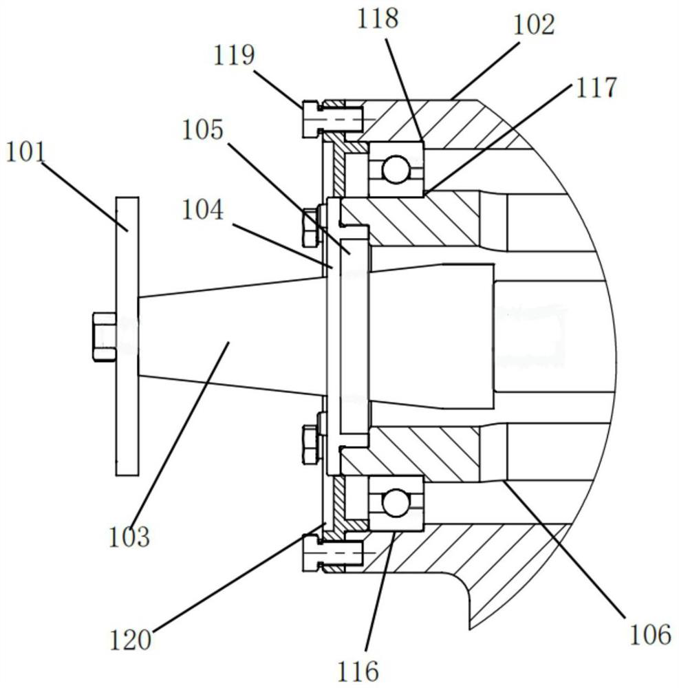
[0043] Such as Figure 1 to Figure 10 As shown, a rotating ultrasonic grinding spindle includes a grinding wheel 101, the grinding wheel 101 is installed at the output end of the horn 103, and a horn flange 104 is arranged in the middle of the horn 103, and the horn flange 104 is arranged in the middle of the horn 103. The horn flange 104 is connected with the end surface of the hollow sleeve 106 through a screw fixing assembly, and a fitting ring 105 is arranged on the right side of the horn flange 104, and the outer peripheral surface of the fitting ring 105 is connected with the hollow sleeve. The inner surface of the sleeve 106 is in contact, and the large-end mandrel of the horn 103 extends into the hollow sleeve 106 to connect with the output end surface of the transducer 107, and a copper sheet 108 is arranged o...


PUM


Abstract

The invention belongs to the technical field of hard and brittle material ultrasonic precision machining, and particularly relates to a rotary ultrasonic grinding machine tool. The rotary ultrasonic grinding machine tool comprises a rotary ultrasonic grinding main shaft, an ultrasonic wave power transmission device, a main shaft clamping and lifting device and a part clamping and feeding device. The rotary ultrasonic grinding main shaft comprises a grinding wheel, wherein the grinding wheel is installed at the output end of an amplitude-change pole, an amplitude-change pole flange is arranged in the middle of the amplitude-change pole and connected with the end face of a hollow sleeve, and a large-end mandrel of the amplitude-change pole stretches into the hollow sleeve and is connected with the output end face of an energy converter. A copper sheet is arranged on the energy converter, a positioning flange is arranged in the middle of the outer surface of the energy converter, the energy converter is connected with the inner surface of the hollow sleeve in a transition fit mode through the positioning flange, the hollow sleeve is installed in a support, and the tail end of the hollow sleeve is connected with an electric main shaft through a coupling. According to the rotary ultrasonic grinding machine tool, the grinding main shaft is directly driven by the electric main shaft, so that the grinding efficiency is improved, the grinding force and the grinding heat are reduced, and the part machining quality is improved.

Description

technical field [0001] The invention belongs to the technical field of ultrasonic precision machining of hard and brittle materials, and in particular relates to a rotary ultrasonic grinding machine tool and its application. Background technique [0002] Hard and brittle materials such as metal matrix composites, ceramic materials, hard alloys, and semiconductor materials are widely used in aerospace, biomanufacturing, and microelectronics manufacturing because of their excellent mechanical, physical, and chemical properties. However, hard and brittle materials are difficult-to-machine materials, which have problems such as poor machinability, low processing efficiency, poor surface quality, and easy cracks and chipping, resulting in high processing costs, which is not conducive to the promotion and use of these materials. [0003] Rotary ultrasonic grinding technology is an effective composite finishing process for hard and brittle materials. Compared with traditional grin...

Claims


Application Information

Patent Timeline
Patent Type & Authority Applications(China)
IPC IPC(8): B24B1/04B24B41/04B24B41/06B24B47/20
CPCB24B1/04B24B41/04B24B41/06B24B47/20
Inventor 秦慧斌马彪冯毅周瑞峰庞学慧王宙辛佳毅郭纪纪
Owner ZHONGBEI UNIV
Why Eureka
Try Eureka