Equipment for optocoupler packaging structure and packaging method

A packaging structure, optocoupler technology, applied in the coupling of optical waveguides, optics, light guides, etc., can solve the problem of reducing the speed of production and the number of unqualified optocoupler products.

Active Publication Date: 2021-07-13
NINGBO QUNXIN MICRO-ELECTRONICS CO LTD
View PDF6 Cites 1 Cited by
  • Summary
  • Abstract
  • Description
  • Claims
  • Application Information

AI Technical Summary

Problems solved by technology

[0007] In order to make up for the deficiencies of the existing technology and solve the problem of using a large number of manual workers to package the optocouplers, reducing the production speed and at the same time, the manually placed optocouplers often have misalignment and increase the number of unqualified products. The invention proposes a method for Equipment and packaging method for optocoupler packaging structure

Method used


Image

  • Equipment for optocoupler packaging structure and packaging method
  • Equipment for optocoupler packaging structure and packaging method
  • Equipment for optocoupler packaging structure and packaging method

Examples


Embodiment 1

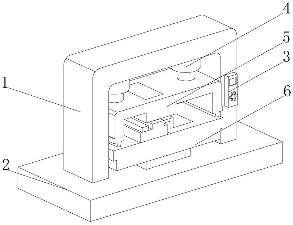
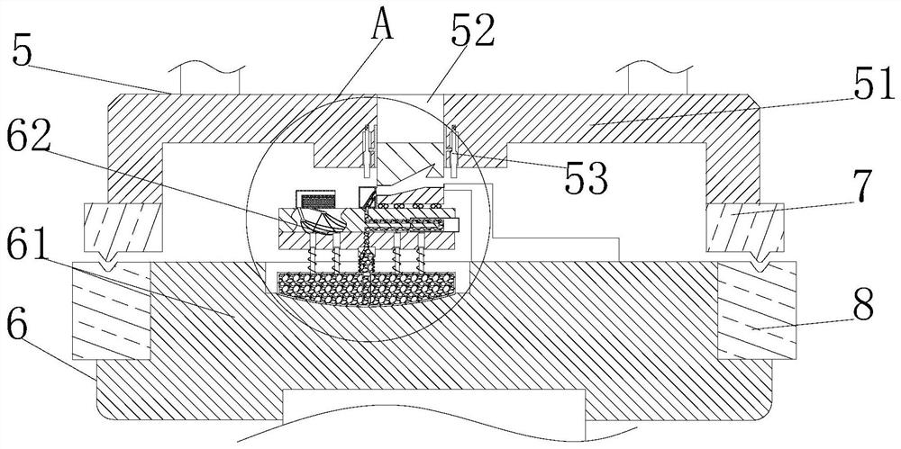
[0037] Such as Figure 2 to Figure 3 As shown, the present invention provides a technical solution: a device for optocoupler packaging structure, including a fixed shell 1 and a base 2, one end of the fixed shell 1 is fixedly connected to the top of the base 2, and the fixed shell 1 One side of the fixed shell 1 is provided with a controller 3, and one side of the fixed shell 1 is fixedly connected with a lifting device 4, and the end of the lifting device 4 away from the fixed shell 1 is fixedly connected with a moving fixture 5, and the top of the base 2 is connected to the moving fixture. The corresponding position of the fixture 5 is fixedly connected with a fixed fixture 6, and one end of the moving fixture 5 close to the fixed fixture 6 is fixedly connected with a positioning projection 7, and the two sides of the fixed fixture 6 are fixedly connected with a positioning projection at a position corresponding to the positioning projection 7. Groove 8, glass windows are pr...

Embodiment 2

[0040] Such as Figure 3 to Figure 9 As shown, the present invention provides a technical solution on the basis of Embodiment 1: a device for an optocoupler packaging structure, the positioning adhesive mechanism 62 includes an adhesive shell 621, and the adhesive shell The top of the body 621 is fixedly connected with an air purification mechanism 622, and the middle part of the viscose shell 621 close to the air purification mechanism 622 is connected with a glue injection mechanism 623, and the air purification mechanism 622 and the glue injection mechanism 623 are far away from the glue One end of the glue shell 621 is fixedly connected with a fixed plate 624 through it, and the top of the fixed plate 624 is fixedly connected with a mounting plate 625. The plate 625 is fixedly connected, and the side of the mounting plate 625 close to the air purification mechanism 622 is fixedly connected with a glue injector 626, and the glue injector 626 communicates with the glue injec...


PUM


Abstract

The invention belongs to the field of packaging equipment, and particularly relates to equipment for an optocoupler packaging structure. The equipment comprises a fixing shell, one end of the fixing shell is fixingly connected with the top of a base, a controller is arranged on one side of the fixing shell, a lifting device is fixingly connected to one side of the fixing shell, a movable clamp is fixingly connected to one end, away from the fixing shell, of the lifting device, a fixing clamp is fixingly connected to the middle of the side, close to the fixing shell, of the base, and glass plates are arranged on the two sides of the fixing shell, so that manual use is reduced, the production speed is increased, meanwhile, dislocation of optical couplers can be avoided, and unqualified products are reduced; according to an optocoupler packaging method, a clamping device exerts pressure on a fixed clamp, a glue injector in a glue injection mechanism injects packaging glue into a gap between an optocoupler upper die plate and an optocoupler lower die plate through the pressure, after glue injection is completed, the pressure is maintained for 5-8 seconds, then a controller controls a movable clamp to move upwards, packaging deviation caused by fatigue of workers is avoided, and the packaging is more convenient and faster.

Description

technical field [0001] The invention belongs to the field of packaging equipment, and in particular relates to equipment and a packaging method for an optocoupler packaging structure. Background technique [0002] Optocoupler isolator is a commonly used optical device. Due to the advancement of science and the extensive application of computers, optocoupler isolators are widely used in military and civilian equipment. Optocoupler isolation is to use optocouplers for isolation. Optocouplers The structure is equivalent to packaging the light-emitting diode and the phototransistor together. The optocoupler isolation circuit makes there is no direct electrical connection between the two isolated circuits to prevent interference caused by electrical connections, especially low-voltage ones. Between the control circuit and the external high voltage circuit. [0003] There are also some technical solutions for optocoupler packaging equipment in the prior art. For example, a Chines...

Claims


Application Information

Patent Timeline
Patent Type & Authority Applications(China)
IPC IPC(8): G02B6/42
CPCG02B6/4251Y02P70/50
Inventor 顾汉玉晁阳吴骏才
Owner NINGBO QUNXIN MICRO-ELECTRONICS CO LTD
Why Eureka
Try Eureka