Filter plate and filter cloth assembly machine for filter press
A filter plate and assembly machine technology for filter presses, applied to assembly machines, metal processing equipment, manufacturing tools, etc., can solve problems such as loss of filtering function, hidden safety hazards, and a large amount of labor
- Summary
- Abstract
- Description
- Claims
- Application Information
AI Technical Summary
Problems solved by technology
Method used
Image
Examples
Embodiment 1
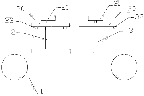
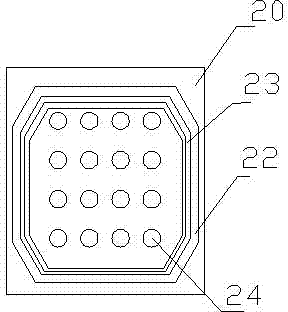
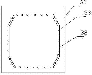
[0024] This embodiment includes a frame, a conveying device 1, a negative pressure device, a filter cloth assembly station 2 and a rubber strip assembly station 3, and the filter cloth assembly station 2 and the rubber strip assembly station 3 are installed on the conveyor belt through the frame. Above the device 1, according to the running direction of the filter plate, the filter cloth assembly station 2 is located before the rubber strip assembly station 3, and the filter cloth assembly station 2 and the rubber strip assembly station 3 are both connected to the negative pressure device. Put the filter plate on the conveying device, the conveying device will transport the filter plate to the filter cloth assembly station, the filter cloth assembly station will suck up the filter cloth through the negative pressure provided by the negative pressure device, and then press the filter plate on the filter plate , the edge of the filter cloth is pressed into the groove of the filte...
Embodiment 2
[0029] This embodiment includes a frame, a conveying device 1, a negative pressure device, a filter cloth assembly station 2 and a rubber strip assembly station 3, and the filter cloth assembly station 2 and the rubber strip assembly station 3 are installed on the conveyor belt through the frame. Above the device 1, according to the running direction of the filter plate, the filter cloth assembly station 2 is located before the rubber strip assembly station 3, and the filter cloth assembly station 2 and the rubber strip assembly station 3 are both connected to the negative pressure device. Put the filter plate on the conveying device, the conveying device will transport the filter plate to the filter cloth assembly station, the filter cloth assembly station will suck up the filter cloth through the negative pressure provided by the negative pressure device, and then press the filter plate on the filter plate , the edge of the filter cloth is pressed into the groove of the filte...
Embodiment 3
[0031] This embodiment includes a frame, a conveying device 1, a negative pressure device, a filter cloth assembly station 2 and a rubber strip assembly station 3, and the filter cloth assembly station 2 and the rubber strip assembly station 3 are installed on the conveyor belt through the frame. Above the device 1, according to the running direction of the filter plate, the filter cloth assembly station 2 is located before the rubber strip assembly station 3, and the filter cloth assembly station 2 and the rubber strip assembly station 3 are both connected to the negative pressure device. Put the filter plate on the conveying device, the conveying device will transport the filter plate to the filter cloth assembly station, the filter cloth assembly station will suck up the filter cloth through the negative pressure provided by the negative pressure device, and then press the filter plate on the filter plate , the edge of the filter cloth is pressed into the groove of the filte...
PUM
 Abstract
Description
Claims
Application Information
 - R&D
- Intellectual Property
- Life Sciences
- Materials
- Tech Scout
- Unparalleled Data Quality
- Higher Quality Content
- 60% Fewer Hallucinations
Browse by: Latest US Patents, China's latest patents, Technical Efficacy Thesaurus, Application Domain, Technology Topic, Popular Technical Reports.
© 2025 PatSnap. All rights reserved.Legal|Privacy policy|Modern Slavery Act Transparency Statement|Sitemap|About US| Contact US: help@patsnap.com


