High-frequency low-loss filter, resonator and preparation method

A low-loss, filter technology, applied in the field of sensors, can solve the problems of increased electrode resistance, large insertion loss, etc., and achieve the effect of reducing electrode resistance, reducing insertion loss, and improving quality factor

Pending Publication Date: 2021-07-09
武汉敏声新技术有限公司
View PDF9 Cites 0 Cited by
  • Summary
  • Abstract
  • Description
  • Claims
  • Application Information

AI Technical Summary

Problems solved by technology

With the advent of the 5G / 6G era, the demand for ultra-high frequency, large bandwidth and low loss is increasing. However, in order to realize the operation of thin film bulk acoustic resonator at high frequency, the electrode thickness and piezoelectric layer thickness are very thin, so It will cause the resistance of the electrode to increase, and a large insertion loss will be introduced when building the filter

Method used


Image

  • High-frequency low-loss filter, resonator and preparation method
  • High-frequency low-loss filter, resonator and preparation method
  • High-frequency low-loss filter, resonator and preparation method

Examples


Embodiment 1

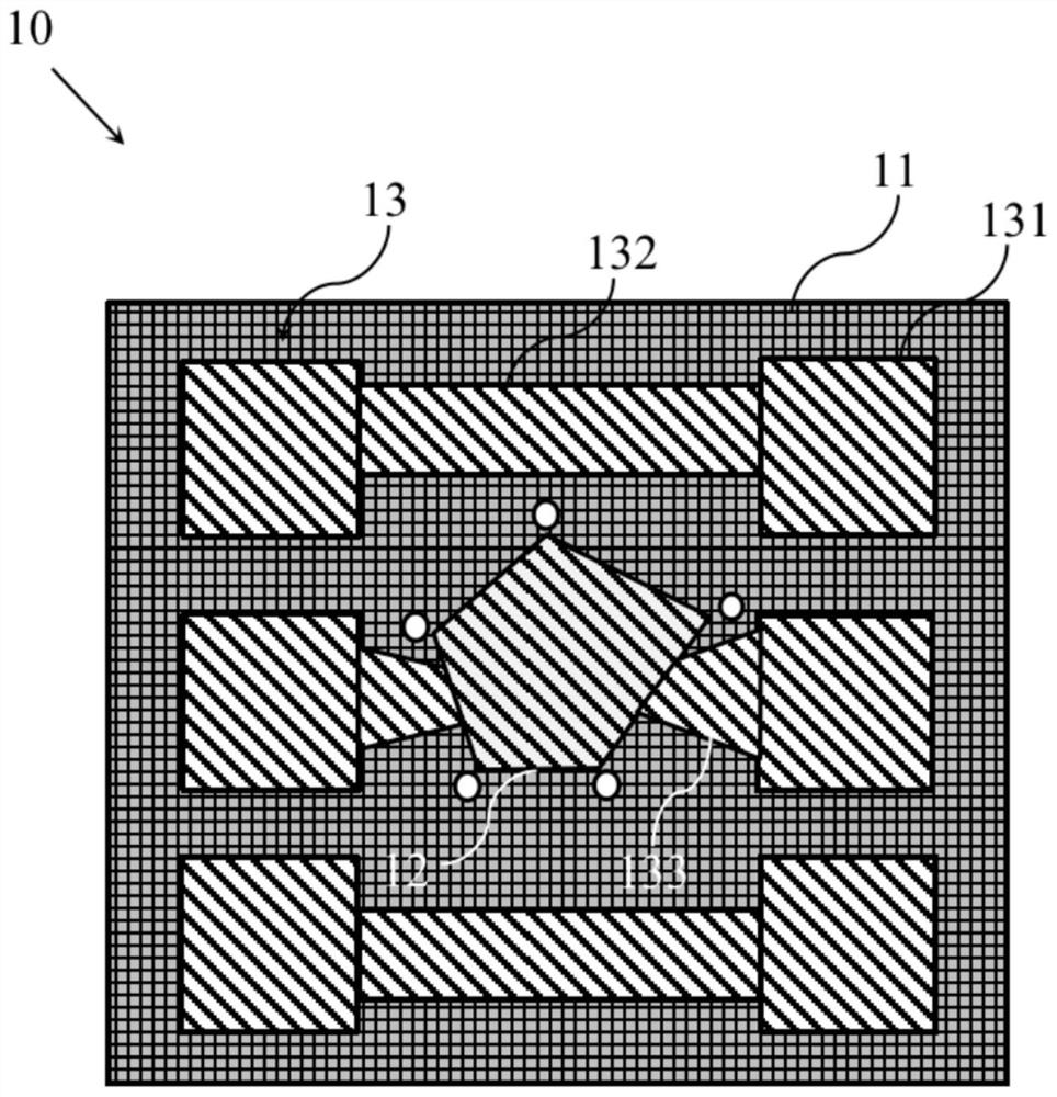
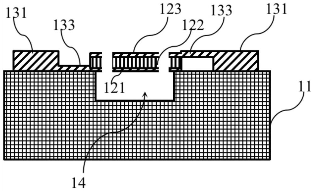
[0046] Such as figure 1 with 2 As shown, the high-frequency low loss resonator 10 provided in the present embodiment includes a substrate 11, an effective resonance portion 12, and a non-active resonance portion 13.

[0047] The middle portion of the substrate 11 has a groove upward opening.

[0048] The effective resonance portion 12 (piezoelectric oscillator stack) is formed on the main region of the substrate 11, and the effective resonance portion 12 includes a bottom electrode 121, a piezoelectric layer 122, and a top electrode 123 from the bottom to top. The groove and the effective resonance portion 12 on the substrate 11 are each form a cavity 14. The effective resonance portion 12 is uniformly provided with a release hole, which is provided for the preparation of the cavity 14. In this embodiment, the patterned effective resonance unit 12 is an irregular five-sided shape.

[0049]The non-active resonant portion 13 is formed on the substrate 11 including a six-piece electr...

Embodiment 2

[0061] Such as Figure 17 with 18 As shown, the high-frequency low loss filter 20 provided in the present embodiment includes a substrate 21, six effective resonance unit 22, and a non-active resonance portion 23.

[0062] The middle region of the substrate 21 is provided with six upward openings, respectively correspond to the six effective resonance units 22, respectively.

[0063] The six effective resonance unit 22 (piezoelectric oscillator piles) are formed on the main region of the substrate 21, and each of the effective resonance units 22 includes a bottom electrode 221, a piezoelectric layer 222, and a top electrode 223 from the bottom to top. The groove and the effective resonance portion 22 on the substrate 21 are each form a cavity 24. The effective resonance portion 22 is uniformly provided with a release hole, which is provided for the preparation of the cavity 24. In this embodiment, the patterned effective resonance unit 22 is an irregular five-sided shape.

[0064] ...


PUM


Abstract

The invention provides a high-frequency low-loss filter, a resonator and a preparation method. The insertion loss can be effectively reduced. The high-frequency low-loss filter provided by the invention comprises: a substrate; at least two effective resonance parts which are formed on the main body area of the substrate; and a non-effective resonance part which comprises a plurality of electrode plates formed on the peripheral area of the substrate, a plurality of connecting wires connected with the electrode plates, and anchor structures connected between any two effective resonance parts, between the effective resonance parts and the electrode plates, and between the effective resonance parts and the connecting wires for electric conduction, and the thickness of the conductive structure in the non-effective resonance part is greater than that of the conductive structure in the effective resonance part.

Description

Technical field [0001] The present invention belongs to the sensor technology, and specific relates to high frequency low loss filters, resonators, and preparation methods. [0002] technical background [0003] With the rapid development of wireless communications, the wireless signal becomes more crowded, and new requirements such as integrated, miniaturization, low power, high performance, low cost are proposed for the filter working in RF band. The traditional sound surface wave filter is increasingly unable to achieve such technical indicators because of the limits of frequencies and endurance, and the like. Thin film acoustic resonator (FBAR) is gradually become a hot spot study of RF filter due to the characteristics of the CMOS process compatible with CMOS process, high quality factor (Q value), low loss, low temperature coefficient, and high power load capacity. [0004] Film Bulk Acoustic Wave Resonator, FBAR can be divided into cavity, silicon back etch type, and solid ...

Claims


Application Information

Patent Timeline
Patent Type & Authority Applications(China)
IPC IPC(8): H03H9/02H03H9/64
CPCH03H9/02H03H9/64
Inventor 孙成亮王雅馨谢英谷曦宇曲远航杨超翔
Owner 武汉敏声新技术有限公司
Why Eureka
Try Eureka