
Rotating device

A technology of rotating device and rotating shaft, which is applied in gaseous chemical plating, metal material coating process, coating, etc., can solve the problems of inability to rotate at high speed, short service life, lower temperature of the center of graphite tray, etc., and achieve stable rotation. Good, improve the service life, the effect of low vacuum leakage rate

Pending Publication Date: 2021-07-09
芯三代半导体科技(苏州)有限公司
View PDF0 Cites 0 Cited by
  • Summary
  • Abstract
  • Description
  • Claims
  • Application Information

AI Technical Summary

Problems solved by technology

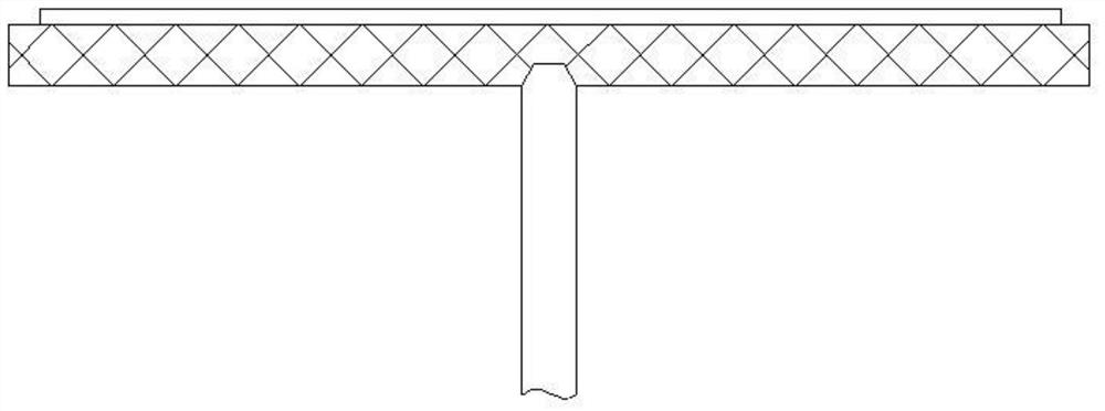
[0004] Among them, the suspension rotating device has the following disadvantages: (1) The rotation stability is poor; (2) The height of the graphite tray fluctuates up and down with the change of the air flow; (3) The temperature of the graphite tray is unstable; (4) It cannot rotate at a high speed
[0005] The central shaft supported rotating device has the following disadvantages: (1) when rotating, the stability of the graphite tray in the horizontal direction is poor; (2) the center of the graphite tray is easy to wear and has a short service life; (3) the center temperature of the graphite tray will decrease, and the center will not Suitable for placing substrates; (4) The graphite tray is prone to cracking; (5) There is a large gap between the graphite tray and the heater, and the reaction gas is easy to corrode the heater

Method used


Image

  • Rotating device
  • Rotating device
  • Rotating device

Examples


Embodiment Construction

[0035] In order to make the above objects, features and advantages of the present invention more comprehensible, specific implementations of the present invention will be described in detail below in conjunction with the accompanying drawings. In the following description, numerous specific details are set forth in order to provide a thorough understanding of the present invention. However, the present invention can be implemented in many other ways different from those described here, and those skilled in the art can make similar improvements without departing from the connotation of the present invention, so the present invention is not limited by the specific embodiments disclosed below.

[0036] In describing the present invention, it should be understood that the terms "center", "longitudinal", "transverse", "length", "width", "thickness", "upper", "lower", "front", " Back", "Left", "Right", "Vertical", "Horizontal", "Top", "Bottom", "Inner", "Outer", "Clockwise", "Counte...


PUM


Abstract

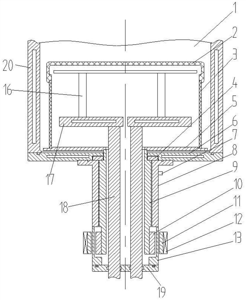
The invention discloses a rotating device which comprises a reactor with a reaction cavity, a sleeve, a rotary shaft, a supporting table, a rotary disc, a graphite tray, heating assembly and a driving assembly, wherein the sleeve is arranged at the bottom of the reactor and comprises a containing cavity and an air inlet communicating with the containing cavity, and the containing cavity communicates with the reaction cavity; the rotary shaft is rotatably arranged in the containing cavity of the sleeve around the axis of the rotary shaft and has a gap with the sleeve, and one end of the rotary shaft extends into the reaction cavity; the supporting table is arranged at the upper end of the sleeve and used for limiting axial movement of the rotary shaft; the rotary disc is connected with one end, extending into the reaction cavity, of the rotary shaft; the graphite tray is supported on the rotary disc; the heating assembly is arranged in the reaction cavity and is used for heating the graphite tray; and the driving assembly is connected with one end, away from the rotary disc, of the rotary shaft and used for driving the rotary shaft to rotate. For the rotating device disclosed by the invention, the rotary shaft is supported in an air suspension mode, rotation is good in smoothness and high in stability nearly without vibration; the rotary shaft is free of hard contact and never abraded, so that the service life can be prolonged; and the extremely low vacuum air leakage rate can be guaranteed without motive sealing.

Description

technical field [0001] The invention relates to the field of chemical vapor deposition (CVD) equipment, in particular to a rotating device. Background technique [0002] CVD equipment (such as MOCVD, SiC-CVD, etc.) used to prepare thin film materials is a high-tech equipment that integrates vacuum, high temperature, high-speed rotation and other technologies. The reaction gas flows through the surface of the heated substrate (substrate), and a chemical reaction occurs to form a single crystal film of GaN, AlN, SiC or other materials. In order to ensure the temperature of the substrate and the uniformity of the airflow field, the graphite tray needs to rotate at a high speed. [0003] At present, there are mainly two kinds of rotating devices in the prior art: one is a suspended rotating device driven by a planetary disk with airflow (such as figure 1 shown), and the other is a central axis supported rotating device (such as figure 2 shown). [0004] Among them, the susp...

Claims


Application Information

Patent Timeline
Patent Type & Authority Applications(China)
IPC IPC(8): C23C16/458
CPCC23C16/4584
Inventor 施建新蒲勇
Owner 芯三代半导体科技(苏州)有限公司
Learn More