
Dust recovery device and processing equipment comprising same

A dust recovery and dust technology, applied in the direction of removing smoke and dust, cleaning methods and utensils, chemical instruments and methods, etc., can solve the problems of inconvenient use, troublesome operation, equipment damage, etc., and achieve the effect of improving collection efficiency

Active Publication Date: 2021-07-09
SHANDONG NINGJIN SPRING
View PDF11 Cites 1 Cited by
  • Summary
  • Abstract
  • Description
  • Claims
  • Application Information

AI Technical Summary

Problems solved by technology

[0002] Composite materials are new materials that people use advanced material preparation technology to optimize the combination of material components with different properties. In the process of processing composite materials, processing equipment needs to be used to polish them to remove their corners. The purpose of the barbs is to make the surface of the material smoother. During the grinding process of the processing equipment, a large amount of dust will be generated. The flying dust will not only enter the gaps on the equipment, causing damage to the equipment, but also adhere to the equipment. The dust is also inconvenient to clean up. At the same time, the dust is inhaled into the lungs of the staff and will also cause damage to health.
[0003] In order to avoid the damage caused by the dust, dust recovery devices are usually used to collect the dust. However, the existing dust recovery devices still have certain deficiencies. It is very troublesome to clean up, and most of the dust collecting hoppers in the existing devices are connected with the device by hoses, which is prone to the phenomenon that the dust collecting hopper cannot be fixed at the dust suction position, while the dust collecting hopper directly fixed on the device It cannot be moved to the dust collection position, which is very inconvenient to use

Method used


Image

  • Dust recovery device and processing equipment comprising same
  • Dust recovery device and processing equipment comprising same
  • Dust recovery device and processing equipment comprising same

Examples


Embodiment Construction

[0030] In order to make the object, technical solution and advantages of the present invention clearer, the present invention will be further described in detail below in conjunction with the accompanying drawings and embodiments. It should be understood that the specific embodiments described here are only used to explain the present invention, not to limit the present invention.

[0031] The implementation of the present invention will be described in detail below in conjunction with specific embodiments, examples of which are shown in the drawings, wherein the same or similar reference numerals represent the same or similar elements or elements with the same or similar functions. The embodiments described below by referring to the figures are exemplary and are only used for explaining the patent, and should not be construed as limiting the patent.

[0032] In the description of this patent, it should be noted that, unless otherwise clearly specified and limited, the terms "...


PUM


Abstract

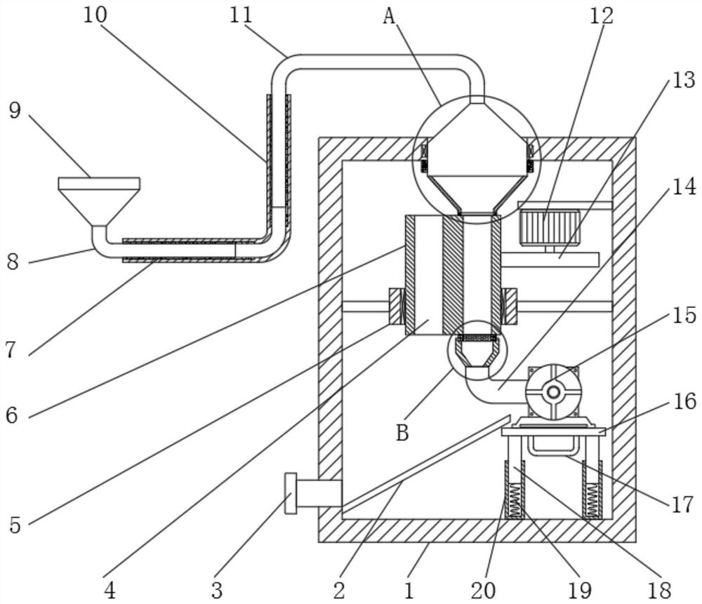
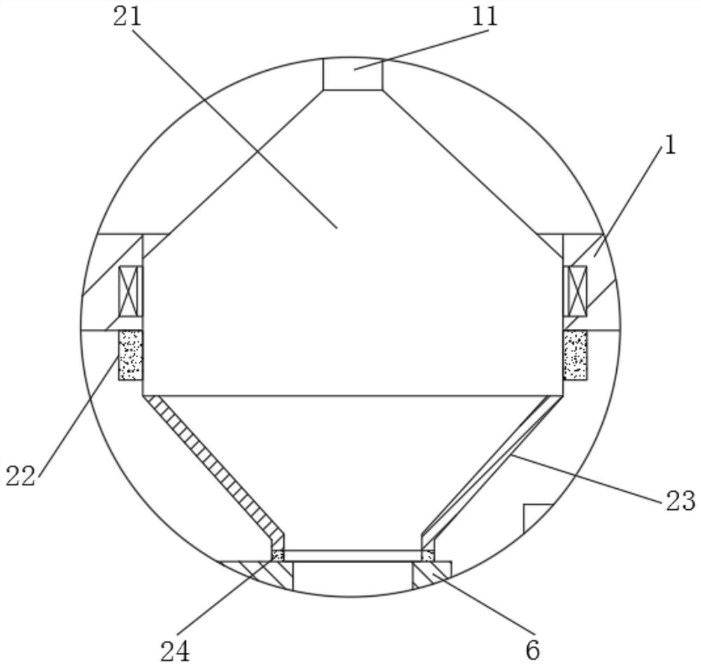
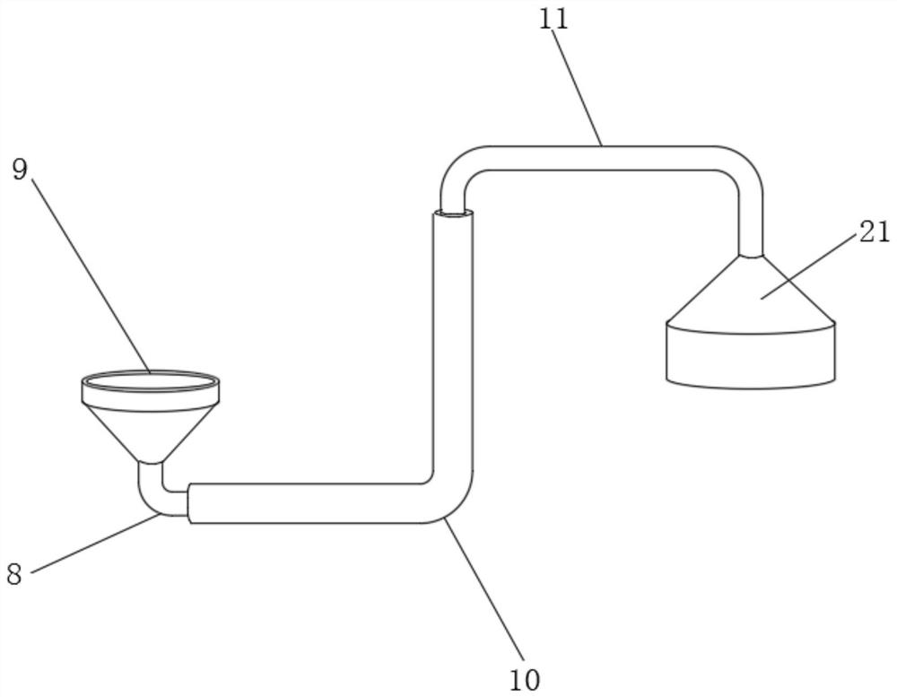
The embodiment of the invention relates to the technical field of dust removal, in particular to a dust recovery device. The dust recovery device is used for collecting dust and comprises a recovery box, a collection mechanism and an air exhaust mechanism arranged in the recovery box, and a dust collection mechanism on the recovery box, wherein the air exhaust mechanism is connected with the collecting mechanism and used for generating dust suction force and sucking dust into the collecting mechanism through the dust collecting mechanism, the collecting mechanism at least comprises a rotating part and a driving part which are rotationally arranged, dust collecting openings which are annularly distributed at equal intervals are formed in the outer wall of the rotating part, the dust collecting openings are attached to the dust collecting mechanism and used for collecting dust when rotating till the axis lines of the dust collecting openings and the axis line of the dust collecting mechanism are located on the same straight line, and the dust collecting mechanism at least comprises a dust collecting pipe, a connecting pipe and a movable pipe. According to the dust recovery device, automatic cleaning and collection of dust are achieved, the problem that the dust collection piece cannot be flexibly moved and fixed is solved, and the device is very convenient to use.

Description

technical field [0001] The invention relates to the technical field of dust removal, in particular to a dust recovery device and processing equipment including the recovery device. Background technique [0002] Composite materials are new materials that people use advanced material preparation technology to optimize the combination of material components with different properties. In the process of processing composite materials, processing equipment needs to be used to polish them to remove their corners. The purpose of the barbs is to make the surface of the material smoother. During the grinding process of the processing equipment, a large amount of dust will be generated. The flying dust will not only enter the gaps on the equipment, causing damage to the equipment, but also adhere to the equipment. The dust is also inconvenient to clean up, and at the same time, the dust is inhaled into the lungs of the staff and will also cause damage to health. [0003] In order to a...

Claims


Application Information

Patent Timeline
Patent Type & Authority Applications(China)
IPC IPC(8): B08B15/00
CPCB08B15/00Y02P70/10
Inventor 高永刚
Owner SHANDONG NINGJIN SPRING
Learn More