
Integral rotary precession type rock roadway cutting machine

A cutting machine, rock technology, applied in tunnels, shaft equipment, mining equipment, etc., can solve problems such as inability to construct

Pending Publication Date: 2021-07-06
金色环掘(北京)科技有限公司
View PDF0 Cites 2 Cited by
  • Summary
  • Abstract
  • Description
  • Claims
  • Application Information

AI Technical Summary

Problems solved by technology

Due to the bottom-up traction of the drilling rig, the raise drilling rig can only construct steeply inclined patios, and cannot construct roadways, inclined shafts and ground wells.

Method used


Image

  • Integral rotary precession type rock roadway cutting machine
  • Integral rotary precession type rock roadway cutting machine
  • Integral rotary precession type rock roadway cutting machine

Examples


Embodiment 1

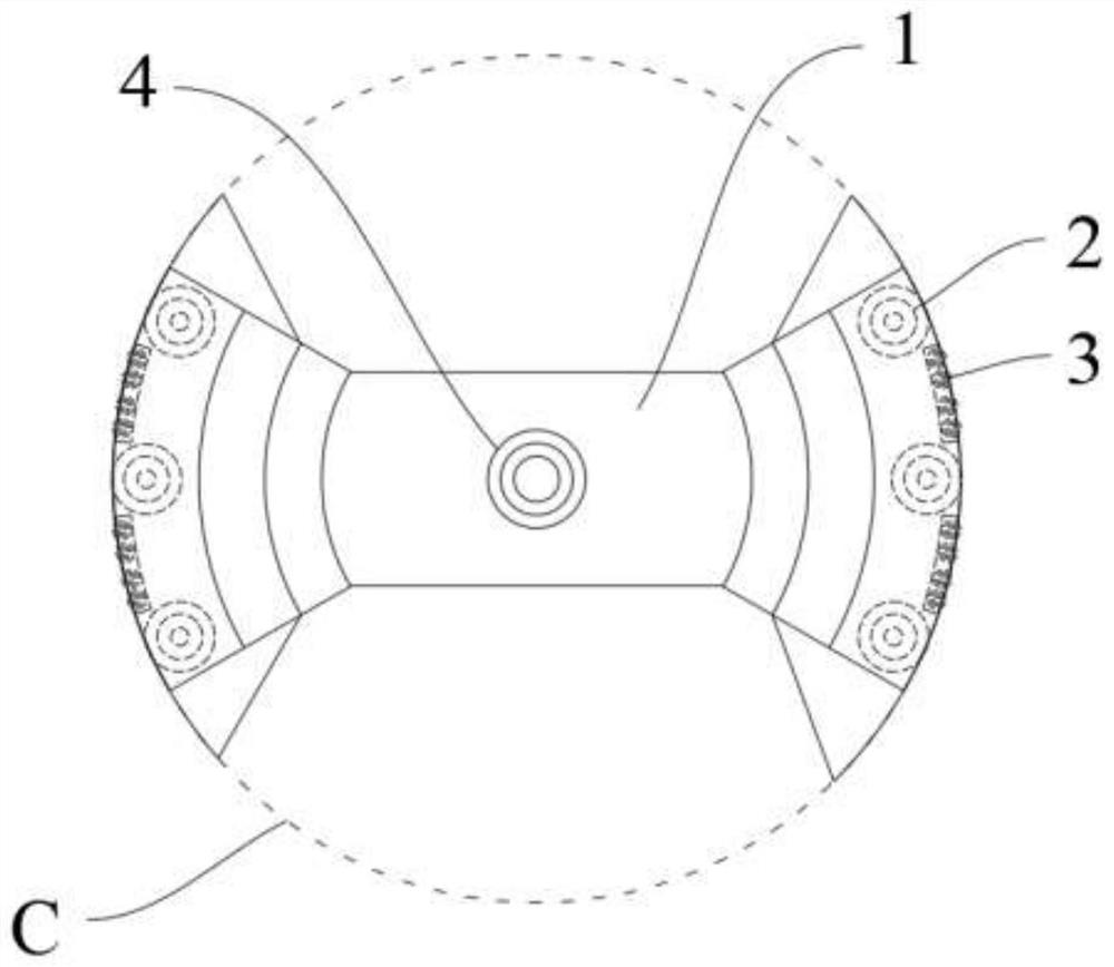
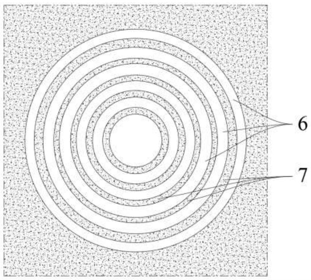
[0038] Such as Figures 1 to 6 As shown, this embodiment provides an integral rotary rotary rock roadway cutting machine, including a rotary cutting platform 1; the outer peripheral side of the rotary cutting platform 1 is provided with a first drive mechanism 2, the first drive mechanism 2 is used to Drive the rotary cutting platform 1 to rotate and drill or retract in the axial direction; the front side of the rotary cutting platform 1 is provided with multiple sets of cutter sets 5; the cutter sets 5 include at least a first cutter 51 and a second cutter 52; The first cutter 51 is used to form the annular drill groove 6, and the second cutter 52 is used to expand the rear end of the annular drill groove in the radial direction; between the annular drill grooves formed by adjacent tool groups 5 Form the thin-walled rock ring 7; the cutter set 5 also includes a third cutter 53 for cutting the thin-walled rock ring 7; wherein, each annular drilling groove 6 corresponds to at l...

Embodiment 2

[0044] The difference between the overall rotary rotary rock roadway cutting machine of this embodiment and the first embodiment is that the distribution range of the conductive slip ring 4 is located in the middle area from the axis center to the outer periphery of the rotary cutting platform 1, specifically as Figure 7 As shown, the drilling groove cut by a kind of integral rotary rotary rock roadway cutting machine of the present embodiment is as follows Figure 8 shown; it should be noted that, Figure 7 The reference sign C in represents the maximum cutting line of the cutter located at the front side of the rotary cutting platform 1 .

Embodiment 3

[0046] An integral rotary rotary rock roadway cutting machine in this embodiment differs from the first embodiment in that: the distribution range of the conductive slip ring 4 is located near the outer peripheral area of ​​the rotary cutting platform 1, specifically as follows Figure 9 shown.

[0047] Embodiment 2 and Embodiment 3 provide different designs of conductive slip ring 4 and rotary cutting platform 1 from Embodiment 1.

[0048] It should be noted, Figure 9 The reference sign C in represents the maximum cutting line of the cutter located at the front side of the rotary cutting platform 1


PUM


Abstract

The invention relates to an integral rotary precession type rock roadway cutting machine. The integral rotary precession type rock roadway cutting machine comprises a rotary cutting platform; a first driving mechanism is arranged on the peripheral side of the rotary cutting platform, and the first driving mechanism is used for driving the rotary cutting platform to rotate and drill or retreat in the axial direction; a plurality of cutter groups are arranged on the front side of the rotary cutting platform; each cutter group at least comprises a first cutter and a second cutter; the first cutter is used for forming an annular drilling groove, and the second cutter is used for expanding the rear end of the annular drilling groove in the radial direction; a rock thin-wall ring is formed between the annular drilling grooves formed by the adjacent cutter groups; and each cutter group further comprises a third cutter used for cutting the corresponding rock thin-wall ring. The integral rotary precession type rock roadway cutting machine can be used for constructing all-directional and angular projects such as a patio, a gate way, an inclined shaft, a ground well and the like, and meanwhile, the machine is simple in structure, low in cost, high in mine underground adaptive capacity and high in cutting and drilling operation speed.

Description

technical field [0001] The invention relates to the field of rock roadway excavation equipment, in particular to an integral rotary rotary rock roadway cutting machine. Background technique [0002] Existing full-section mechanized tunneling equipment for rock roadways are all roadheaders that apply rolling damage and a small amount of cutting damage to the working face, mainly rock-type shield machines and raise drilling rigs. [0003] Among them, the rock shield machine relies on external machinery or hydraulic pressure to propel the cutter head and the body as a whole, and at the same time, the cutter is pressed into the rock through strong pressure, and then the cutter head is rotated by a strong torque, so as to implement rolling and crushing on the rock working face. Cutting operation, which involves a large amount of rolling and a small amount of cutting on the rock working face, is a high-energy-consuming destruction method, so it requires high power and high mechani...

Claims


Application Information

Patent Timeline
IPC IPC(8): E21D9/11E21D9/10E21D3/00E21D1/06E21D9/02
CPCE21D1/06E21D3/00E21D9/02E21D9/1086E21D9/112
Inventor 邓义坡邓秉灿孟小玲
Owner 金色环掘(北京)科技有限公司
Learn More