
High-speed wire rod production system with reducing and sizing unit and method

A high-speed wire rod and production system technology, which is applied in workpiece surface treatment equipment, metal rolling, manufacturing tools, etc., can solve the problems of reducing the yield of finished products, product flowability, large size, and long spacing.

Pending Publication Date: 2021-07-06
CISDI ENG CO LTD +1
View PDF0 Cites 4 Cited by
  • Summary
  • Abstract
  • Description
  • Claims
  • Application Information

AI Technical Summary

Problems solved by technology

However, after adding and reducing the sizing unit, due to the long distance between the finishing rolling unit and the reducing and sizing unit, a tension-free free state head and tail rolled piece is formed at the head and tail, and the size of the rolled piece in this section is larger than that in the stable rolling stage. , It is easy to form a big head and a big tail when producing rebar, and even "ears" will appear at the head and tail when producing round steel, which greatly reduces the yield and product passability

Method used

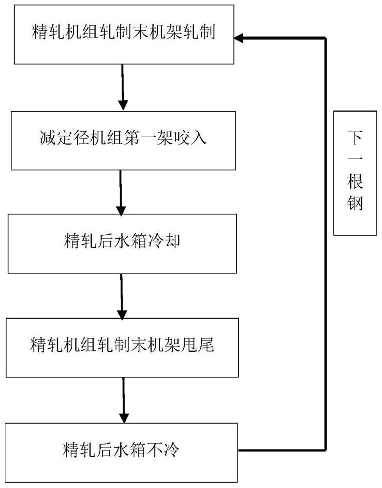

Image

  • High-speed wire rod production system with reducing and sizing unit and method
  • High-speed wire rod production system with reducing and sizing unit and method
  • High-speed wire rod production system with reducing and sizing unit and method

Examples


Embodiment Construction

[0037] Embodiments of the present invention are described below through specific examples, and those skilled in the art can easily understand other advantages and effects of the present invention from the content disclosed in this specification. The present invention can also be implemented or applied through other different specific implementation modes, and various modifications or changes can be made to the details in this specification based on different viewpoints and applications without departing from the spirit of the present invention. It should be noted that the diagrams provided in the following embodiments are only schematically illustrating the basic concept of the present invention, and the following embodiments and the features in the embodiments can be combined with each other in the case of no conflict.

[0038] Wherein, the accompanying drawings are for illustrative purposes only, and represent only schematic diagrams, rather than physical drawings, and should...


PUM


Abstract

The invention belongs to the field of high-speed wire rod production in the ferrous metallurgical industry, and relates to a high-speed wire rod production system with a reducing and sizing unit and a method. The system comprises a blank heating device, a roughing mill unit, a roughing mill unit rear flying shear, an intermediate mill unit, an intermediate mill unit rear flying shear, a pre-finishing mill unit, a loop between pre-finishing mill units, a pre-finishing mill unit rear flying shear, a finishing mill unit front loop, a finishing mill unit, a finishing mill unit rear water tank, a reducing mill unit front flying shear device, a pinch roll, a cut-off shear, a reducing and sizing mill or a reducing mill, a reducing and sizing unit rear water tank, a silking machine front pinch roll, a silking machine, an air cooling line and a collecting device. According to the method, the size control precision of the free section between the reducing and sizing unit and the finishing mill unit is improved, the size out-of-tolerance of the head and the tail is reduced, the size cleaning performance of a final product is improved, the yield is increased, the accident occurrence probability of the area is reduced, the fault processing time in the production process is shortened, the rolling mill operation rate is increased, and the income is increased.

Description

technical field [0001] The invention belongs to the field of high-speed wire rod production in the iron and steel metallurgy industry, and relates to a high-speed wire rod production system and method equipped with a reducing and sizing unit. Background technique [0002] In order to reduce production costs and achieve green development goals, it has become the choice of more and more users to add or subtract sizing units or reducing units after the traditional finishing unit. After the finishing unit is added a reducing and sizing unit, the cooling before and after the finishing rolling unit and after the reducing and sizing unit can be combined with the low-temperature and high-pressure rolling of the reducing and sizing unit to realize full-line controlled rolling and controlled cooling. In this way, on the premise of not adding microalloying elements, the austenite grains can be refined through low temperature, high pressure and rapid cooling and other production methods...

Claims


Application Information

Patent Timeline
Patent Type & Authority Applications(China)
IPC IPC(8): B21B1/16B21B15/00B21B37/50B21B37/74B21B39/02B21B45/00B21B45/02
CPCB21B1/16B21B15/0007B21B37/50B21B37/74B21B39/02B21B45/004B21B45/0209B21B2015/0014B21B2045/0212
Inventor 周民马靳江谭成楠樊泽兴白亚斌牛强
Owner CISDI ENG CO LTD
Learn More