Body shaping device for drama performance
A training device and body technology, which is applied in the field of body training and can solve the problems of lack of massage, hot compress, trouble, and movement of arch-frame trainers.
- Summary
- Abstract
- Description
- Claims
- Application Information
AI Technical Summary
Problems solved by technology
Method used
Image
Examples
Embodiment 1
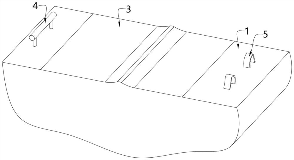
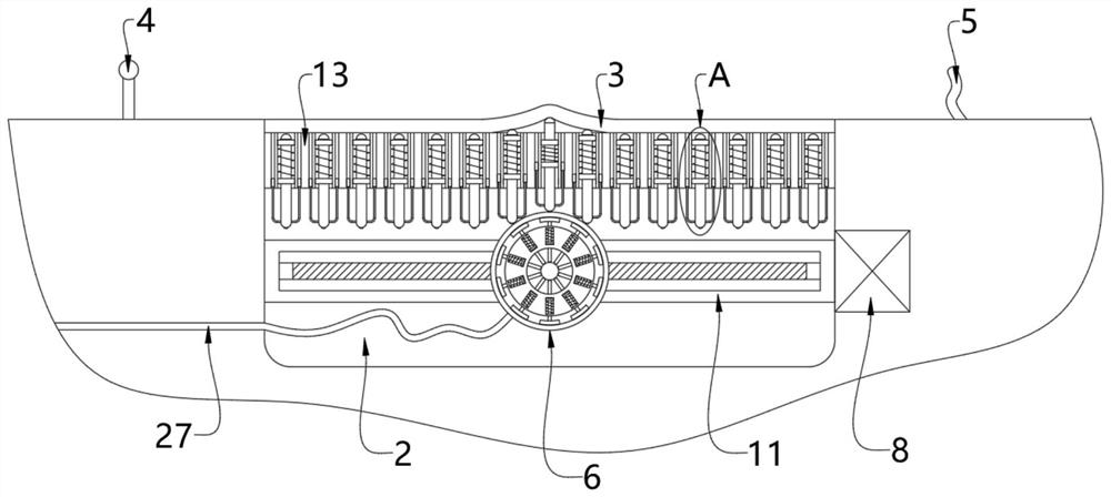
[0058] see Figure 1-5 , a body training device for dramatic performances, comprising a paving layer 1, the paving layer 1 is the ground inside and around the building, and may also be the surface of a floor, the inside of the paving layer 1 is formed with an inner groove 2, and the inner groove 2 The top of the inner wall is fixedly installed with an elastic rubber pad 3, and the bottom of the elastic rubber pad 3 is provided with a horizontal plate 13, and the inside of the horizontal plate 13 is uniformly provided with a vertical groove 14, and the inside of the vertical groove 14 is inserted with a push rod 16, connected The pretensioning device between the push rod 16 and the inner wall of the vertical groove 14 is used to provide vertical downward elastic support for the push rod 16;
[0059] The lower part of the horizontal plate 13 is provided with a jacking tube 6, and the two ends of the jacking tube 6 are provided with a connecting sleeve 7. The inner wall of the in...
Embodiment 2
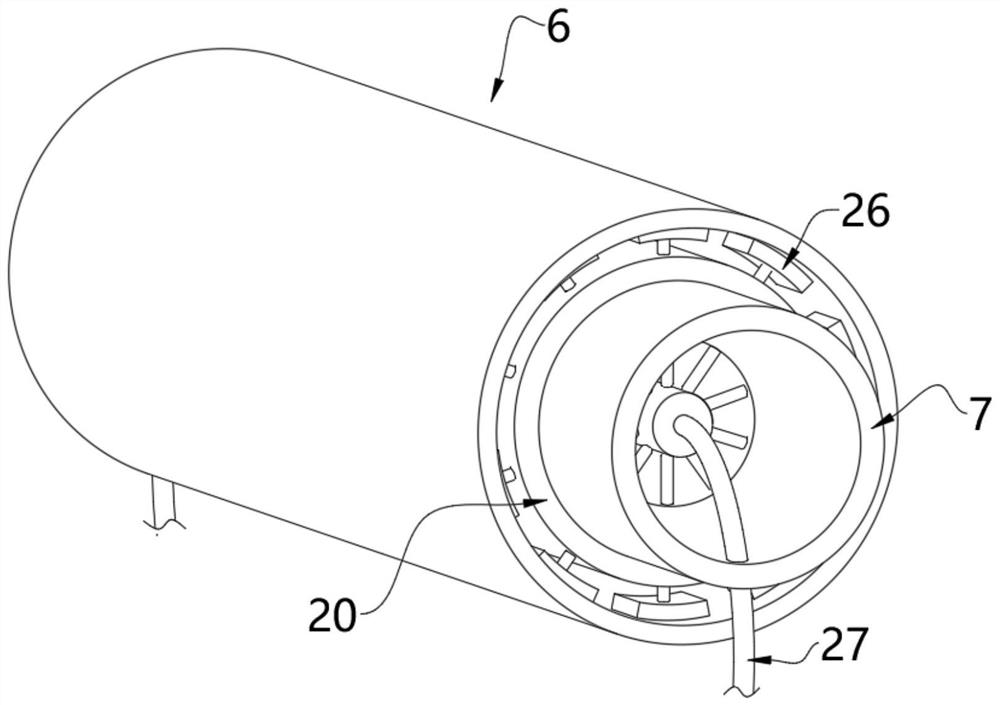
[0064] see image 3 and Figure 7 , on the basis of Embodiment 1, the jacking cylinder 6 includes a columnar airbag 19, an inner cylinder 20 and an elastic rubber ring 21, the inner cylinder 20 is arranged inside the elastic rubber ring 21, and the cylindrical airbag 19 is arranged inside the inner cylinder 20;
[0065] A cavity 22 is also formed inside the wall body of the inner cylinder 20, and a linkage rod 23 is movable inside the cavity 22. One end of the linkage rod 23 extends to the inside of the inner cylinder 20 and is against the outer wall of the columnar airbag 19. The other end of 23 extends to the outside of the inner cylinder 20 and is fixedly connected with a diameter-expanding plate 26, and the diameter-expanding plate 26 is fixedly connected with the elastic rubber ring 21;
[0066] The outer wall of the linkage rod 23 is also fixedly equipped with a push plate 24, a second spring 25 is fixedly connected between the outer wall of the push plate 24 and the in...
Embodiment 3
[0069] see Figure 6 , Figure 8 , Figure 9 , Figure 10 and Figure 11 , on the basis of Embodiment 1 and Embodiment 2, a storage battery 29 is provided in the lower half of the interior of the ejector rod 16, a water cavity 31 is formed in the upper half of the interior of the ejector rod 16, and a heating coil 30 is provided in the interior of the water chamber 31 , the top of the inner wall of the water cavity 31 is formed with an internal thread 32, and the inner wall of the internal thread 32 is threadedly connected with a connecting cap 33;
[0070] The left and right sides of the outer wall of the push rod 16 are fixedly equipped with branch pipes 35, and the top of the branch pipe 35 is fixedly equipped with a sealing column 36, which is movably arranged on the inner wall of the column groove 38, and the column groove 38 is set inside the horizontal plate 13;
[0071] The inner wall of the water chamber 31 is provided with a steam pipe 34, and the end of the stea...
PUM
 Abstract
Description
Claims
Application Information
 - Generate Ideas
- Intellectual Property
- Life Sciences
- Materials
- Tech Scout
- Unparalleled Data Quality
- Higher Quality Content
- 60% Fewer Hallucinations
Browse by: Latest US Patents, China's latest patents, Technical Efficacy Thesaurus, Application Domain, Technology Topic, Popular Technical Reports.
© 2025 PatSnap. All rights reserved.Legal|Privacy policy|Modern Slavery Act Transparency Statement|Sitemap|About US| Contact US: help@patsnap.com


