Eureka AIR delivers breakthrough ideas for toughest innovation challenges, trusted by R&D personnel around the world.

High-safety dehumidification waterproof switch device for bathroom

A high-safety, switching device technology, applied in the direction of electric switches, electrical components, separation methods, etc., can solve the problems of low safety, leakage and conduction, and not very convenient operation, etc., achieve a high degree of automation, avoid continuous use, increase The effect of convenience

Inactive Publication Date: 2021-07-02
嘉兴努鹤贸易有限公司
View PDF0 Cites 0 Cited by
  • Summary
  • Abstract
  • Description
  • Claims
  • Application Information

AI Technical Summary

Problems solved by technology

[0002] There are often sockets inside the bathroom to facilitate the use of electrical appliances such as hair dryers and curling irons. Due to the relatively high requirements for the area of ​​the bathroom in the dry-wet separation type bathroom, and the construction cost is higher than the traditional bathroom design, the dry-wet separation type bathroom cannot satisfy everyone. However, when bathing in a bathroom that is not dry and wet, the water vapor generated will flood the entire bathroom, and the surface of the socket that the moisture will condense. When using electrical appliances at this time, there is a risk of leakage and conduction, and the safety of use is relatively low.
In the existing waterproof switch, a waterproof cover is added outside the switch to enhance the safety of the switch, but it is not very convenient to operate

Method used


Image

  • High-safety dehumidification waterproof switch device for bathroom
  • High-safety dehumidification waterproof switch device for bathroom
  • High-safety dehumidification waterproof switch device for bathroom

Examples


Embodiment 1

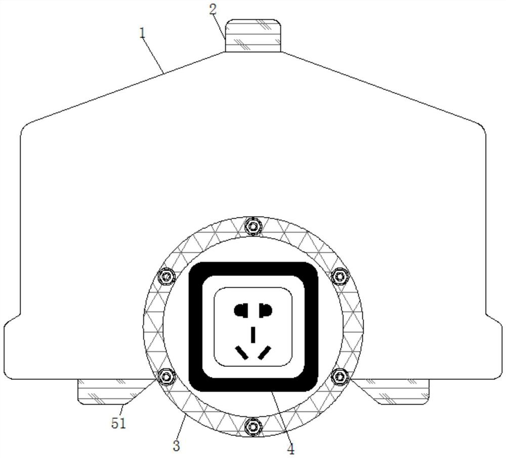
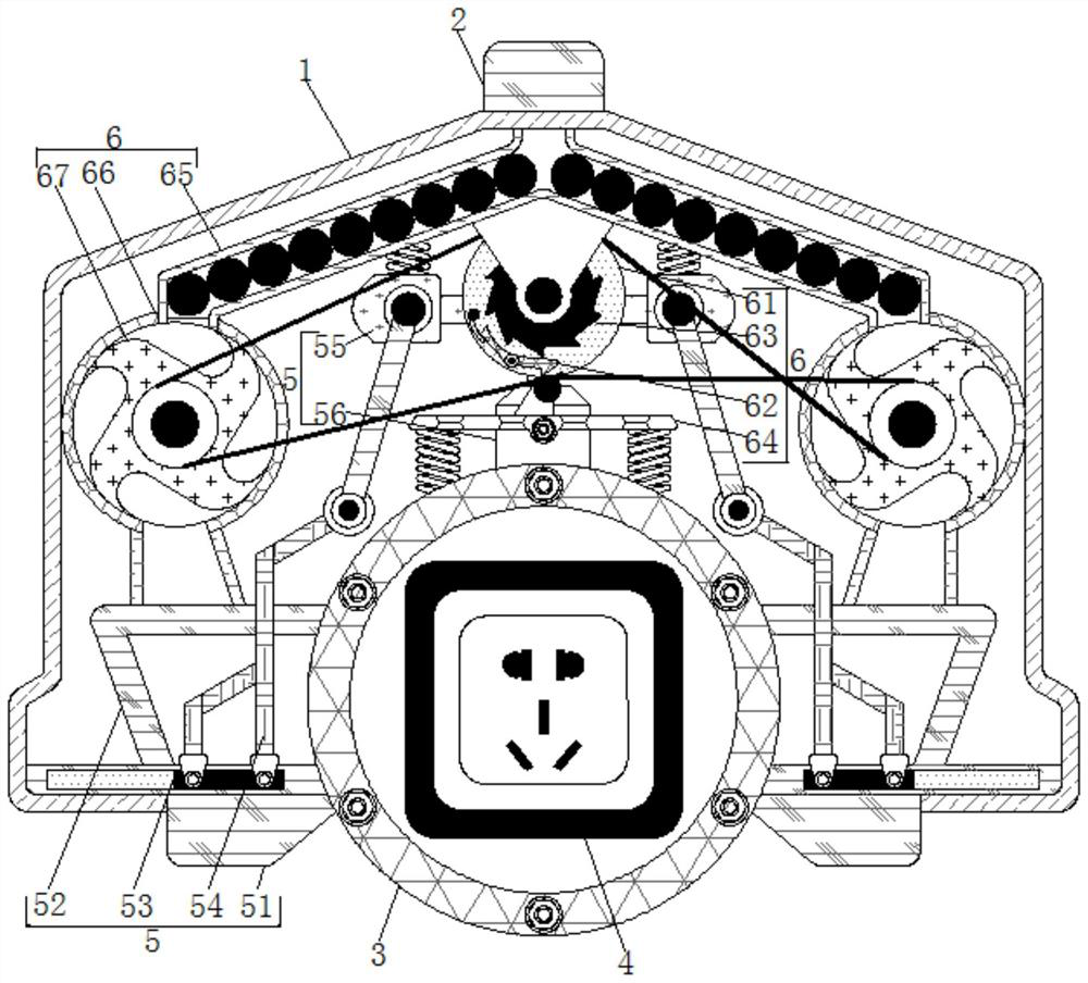
[0024] see Figure 1-2 , a high-safety dehumidification and waterproof switchgear for toilets, comprising a housing 1, the top of the housing 1 is fixedly connected with a storage box 2, the bottom of the housing 1 is fixedly connected with a mounting plate 3, and the inside of the mounting plate 3 is provided with The air vent, the mounting plate 3 is in the shape of a circle, the size of the internal port matches the size of the protective body 4, the air vent provided inside the mounting plate 3 is convenient for the dehumidification pills arranged in the shell 1 to absorb the moisture around the protective body 4 , to prevent moisture in the air from condensing on the surface of the protective body 4, wet the protective body 4, and play a waterproof role. Material mechanism 5 comprises waste material box 51, and waste material box 51 has two and same specification, and two waste material boxes 51 are arranged on the both sides of mounting plate 3, and the top of waste mate...

Embodiment 2

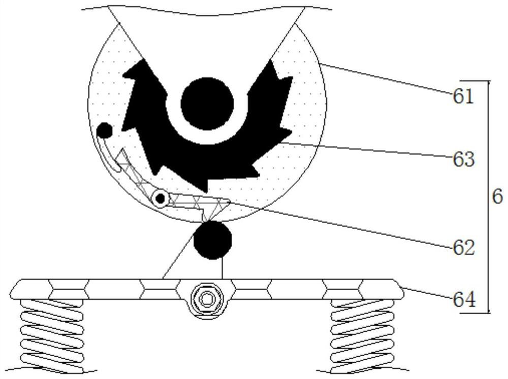
[0026] see Figure 1-3 , a high-safety dehumidification and waterproof switchgear for toilets, comprising a housing 1, the top of the housing 1 is fixedly connected with a storage box 2, the bottom of the housing 1 is fixedly connected with a mounting plate 3, and the inside of the mounting plate 3 is provided with The air vent, the mounting plate 3 is in the shape of a circle, the size of the internal port matches the size of the protective body 4, the air vent provided inside the mounting plate 3 is convenient for the dehumidification pills arranged in the shell 1 to absorb the moisture around the protective body 4 , to prevent moisture in the air from condensing on the surface of the protective body 4, wet the protective body 4, and play a waterproof role. The outer side of material mechanism 5 is provided with feeding mechanism 6, and feeding mechanism 6 comprises turntable 61, and the outside of turntable 61 is movably connected with first stay cord and second stay cord, ...

Embodiment 3

[0028] see Figure 1-3 , a high-safety dehumidification and waterproof switchgear for toilets, comprising a housing 1, the top of the housing 1 is fixedly connected with a storage box 2, the bottom of the housing 1 is fixedly connected with a mounting plate 3, and the inside of the mounting plate 3 is provided with The air vent, the mounting plate 3 is in the shape of a circle, the size of the internal port matches the size of the protective body 4, the air vent provided inside the mounting plate 3 is convenient for the dehumidification pills arranged in the shell 1 to absorb the moisture around the protective body 4 , to prevent moisture in the air from condensing on the surface of the protective body 4, wet the protective body 4, and play a waterproof role. Material mechanism 5 comprises waste material box 51, and waste material box 51 has two and same specification, and two waste material boxes 51 are arranged on the both sides of mounting plate 3, and the top of waste mate...


PUM


Abstract

The invention relates to the technical field of waterproof switches, and discloses a high-safety dehumidification waterproof switch device for a bathroom. The switch device comprises a shell, and the top of the shell is fixedly connected with a storage box; an air cylinder drives a movable rod to move up and down, a clamping plate is made to be far away and then move to a through opening of a processing box, the position of the clamping plate is controlled, a supporting effect is achieved on dehumidification pills in the processing box, the dehumidification pills are convenient to place, after dehumidification is completed, the dehumidification pills adsorbing moisture are removed and collected, a moving rod moves up and down to drive a stop rod to move synchronously, the stop rod gets away from and then gets close to a follow-up rod, so that part of the rod body of the follow-up rod gets close to and then gets away from a ratchet wheel, the ratchet wheel drives a rotating disc to intermittently rotate through the follow-up rod, the rotating disc drives two transferring discs to rotate in the opposite directions, the transferring discs sequentially transfer the dehumidification pills in the branch pipes of the material pipes into the processing box, automatic and quantitative supply of the dehumidification pills is achieved, and continuous waterproof and dehumidification operation of the switch is facilitated.

Description

technical field [0001] The invention relates to the technical field of waterproof switches, in particular to a high-safety dehumidification and waterproof switch device for toilets. Background technique [0002] There are often sockets inside the bathroom to facilitate the use of electrical appliances such as hair dryers and curling irons. Due to the relatively high requirements for the area of ​​the bathroom in the dry-wet separation type bathroom, and the construction cost is higher than the traditional bathroom design, the dry-wet separation type bathroom cannot satisfy everyone. However, when bathing in a bathroom that is not dry and wet, the water vapor generated will flood the entire bathroom, and the surface of the socket that the moisture will condense. When using electrical appliances at this time, there is a risk of leakage and conduction, and the safety of use is relatively low. . In the existing waterproof switch, a waterproof cover is added outside the switch t...

Claims


Application Information

Patent Timeline
Patent Type & Authority Applications(China)
IPC IPC(8): H01H9/04B01D53/26
CPCB01D53/261H01H9/04
Inventor 朱莹
Owner 嘉兴努鹤贸易有限公司
Why Eureka
Eureka Blog
Learn More