A self-cleaning safety separator, an integrated separation and cleaning system using the separator, and a method for using the system

A safe and separator technology, applied in the field of oil drilling, can solve the problems affecting normal operation, no liquid in the outlet pipe, long cleaning time, etc., and achieve the effect of sedimentation and separation, ingenious and reasonable structure, and rapid cleaning

Active Publication Date: 2021-11-19
广汉市思明石油钻采设备配套有限公司
View PDF19 Cites 0 Cited by
  • Summary
  • Abstract
  • Description
  • Claims
  • Application Information

AI Technical Summary

Problems solved by technology

[0005] However, in the process of use, it was found that after the separation work of the equipment, a lot of mud adhered to the pipe wall of the liquid inlet, as well as the inner and outer cylinder walls, tank walls, deflectors, etc. If it is not cleaned in time , it will be bonded and solidified on the corresponding wall plate soon, so when cleaning, it is necessary to disassemble the equipment, soak it and then scrape off the agglomerated foreign matter, so it is very difficult to clean the liquid-gas separator, which requires a lot of manpower and material resources , and requires a long cleaning time; in addition, in practical applications, it is found that the operator often does not clean the separator, or even forgets to clean the separator, resulting in the mud seriously blocking each pipe or each inlet / outlet, resulting in No liquid comes out of the liquid outlet pipe, causing the drilling fluid to spray out from the exhaust port, which seriously affects the normal operation

Method used


Image

  • A self-cleaning safety separator, an integrated separation and cleaning system using the separator, and a method for using the system
  • A self-cleaning safety separator, an integrated separation and cleaning system using the separator, and a method for using the system
  • A self-cleaning safety separator, an integrated separation and cleaning system using the separator, and a method for using the system

Examples


Embodiment 1

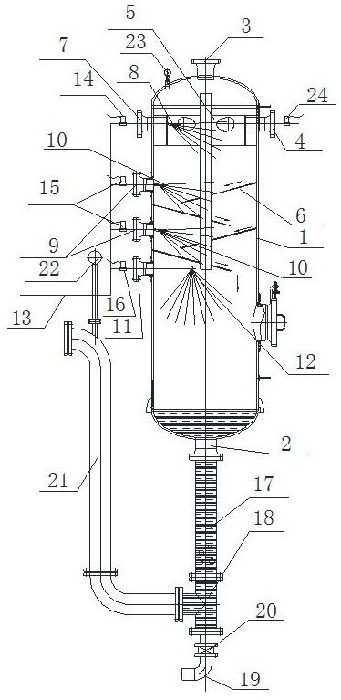
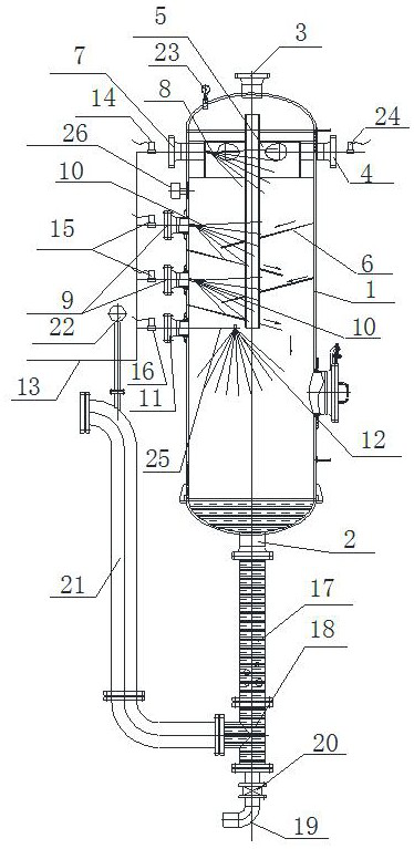
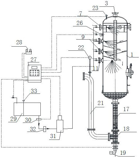
[0042] A self-cleaning safety type separator belongs to the technical field of oil drilling, reference figure 1 , including a tank body 1, the lower part of the tank body 1 is connected with a discharge port 2; the upper part is connected with an exhaust pipe 3 and a fluid input pipe 4, a separation mechanism 5 is fixed above the inside of the tank body 1, and the bottom of the separation mechanism 5 inside the tank body 1 is staggered A deflector 6 is provided, and a cleaning hole I7 is provided on the wall of the tank body 1 flush with the separation mechanism 5, and a high-pressure nozzle I8 is installed at one end of the cleaning hole I7 in the tank body 1, and each guide A cleaning hole II9 is ​​provided on the wall of the tank body 1 above the flow plate 6, and a high-pressure nozzle II10 is installed at one end of the cleaning hole II9 in the tank body 1, and on the inner wall of the tank body 1 below the flow guide plate 6 at the bottom end A cleaning hole III11 is ope...

Embodiment 2

[0047] This embodiment is a further improvement on Embodiment 1, the difference is that the inclination of the deflectors 6 is 15°, and the distance between adjacent deflectors 6 is 100 cm.

Embodiment 3

[0049] Compared with Embodiments 1 and 2, this embodiment differs in that, with reference to Figure 4 , the nozzle direction of the high-pressure nozzle II10 is consistent with the inclination direction of the deflector 6 .

[0050] The high-pressure nozzle I8 and the high-pressure nozzle II10 in this embodiment use solid cone nozzles, and the annular high-pressure nozzle 12 uses multi-head combination nozzles. During installation, contact with drilling fluid should be avoided as much as possible, which will affect normal use.


PUM


Abstract

The invention discloses a self-cleaning safety type separator and an integrated separation and cleaning system using the separator, belonging to the technical field of petroleum drilling, and can solve the problem that the liquid-gas separator in the prior art is inconvenient to clean and difficult to clean , long cleaning time, labor-intensive and other problems, the structure is ingenious, and can be directly improved and optimized on the previous equipment. In addition, a method of using the system is provided, so that the self-cleaning safety separator can efficiently complete the separation task. , can quickly complete the cleaning of the equipment, and save water resources as much as possible.

Description

technical field [0001] The invention belongs to the technical field of petroleum drilling, and in particular relates to a self-cleaning safety separator, an integrated separation and cleaning system using the separator and a method for using the system. Background technique [0002] In the oil drilling industry, liquid-gas separation technology is widely used in industry, the main purpose is to separate and eliminate harmful substances or recover useful substances. In this industry, the principles of liquid-gas separation technology mainly include gravity sedimentation, inertial collision, centrifugal separation, baffle separation, screen separation, ultrafiltration separation, seasoning separation, electrostatic attraction, dismantling, etc. [0003] In the liquid-gas separator commonly used in the prior art, the drilling fluid enters the separator tangentially from the liquid inlet of the separator, falls on a series of inner baffles along the inner wall, collides, increas...

Claims


Application Information

Patent Timeline
Patent Type & Authority Patents(China)
IPC IPC(8): B01D19/00B08B9/093B08B13/00E21B21/06
CPCB01D19/0042B01D19/0052B08B9/0813B08B13/00E21B21/067
Inventor 徐思明王成刚眭伯涛成生华莫帅罗勇黄强谭孝洪吴军刘晗
Owner 广汉市思明石油钻采设备配套有限公司
Why Eureka
Try Eureka