Gas turbine interstage sealing structure

A technology of sealing structure and gas turbine, which is applied in the direction of mechanical equipment, engine components, machines/engines, etc. It can solve problems such as pressure differential imbalance, wheel burnout, and small tooth tip clearance, so as to reduce the possibility of seal failure and avoid movement and static The effect of rubbing and increasing the radial clearance

Active Publication Date: 2021-12-24
浙江燃创透平机械有限公司
View PDF11 Cites 0 Cited by
  • Summary
  • Abstract
  • Description
  • Claims
  • Application Information

AI Technical Summary

Problems solved by technology

[0004] The problem existing in the prior art is that for the upstream seal: due to the limitation of strength, the axial position of the installation groove is limited, and the axial length of the extended end 6 of the wheel disk seal cannot be too large. Due to the limitation of the axial position of the installation groove, the entrance of the disc cavity is generally provided with a single-tooth seal (such as figure 1 shown), but due to the difference in expansion between the rotor and the stator and the difference in axial displacement, the seal may fail (such as figure 2 As shown in the enlarged part of the seal tooth B), the failure of the seal will cause the pressure difference between the upstream dynamic and static disc cavity 4 and the dynamic and static disc cavity 8 to be unbalanced, and the seal of the disc cavity cannot meet the requirements. If the cavity is overheated, the unit will stop, and if it is serious, the wheel will be burned
[0008] 1. The existing sealing tooth is a single tooth. Due to the difference in expansion between the rotor and the stator and the difference in axial displacement, the seal may fail, resulting in overheating of the disc cavity, shutdown of the unit, and even burning of the wheel disc
[0009] 2. For the single-tooth structure, under the same sealing requirements, the tooth tip clearance will be set relatively small, and the risk of dynamic and static friction will easily occur during operation
[0010] 3. The sealing structure composed of the honeycomb seal and the high and low tooth seal, in the event of dynamic and static friction, the damage of the honeycomb seal is irreversible, the replacement cost is high, the damage of the rotor high and low teeth is irreversible, and will not be replaced during overhaul, and the performance of the unit decreases year by year
[0011] 4. The left and right seals of the existing structure are an integrated structure. If any side seal is damaged, the entire part needs to be disassembled, repaired or even replaced, and the cost is high

Method used


Image

  • Gas turbine interstage sealing structure
  • Gas turbine interstage sealing structure
  • Gas turbine interstage sealing structure

Examples


Embodiment approach

[0074] The upstream extension end of the inner shroud of the stator blade is located on the left side of the inner shroud of the stator blade, and the installation section of the left half of the turbine interstage seal structure is connected to the outer extension end of the inner shroud of the stator blade through bolts. connect;

[0075] The downstream extension end of the inner shroud of the stator blade is located on the right side of the inner shroud of the stator blade, and the installation section of the right half of the turbine interstage seal structure is connected to the outer extension end of the inner shroud of the stator blade through bolts. connect.

[0076] As a preferred embodiment, the working section of the right half of the turbine interstage seal structure is fixed on the connecting section of the right half of the turbine interstage seal structure by punching and riveting,

[0077]Or, the working section of the right half of the turbine interstage seal ...

Embodiment 1

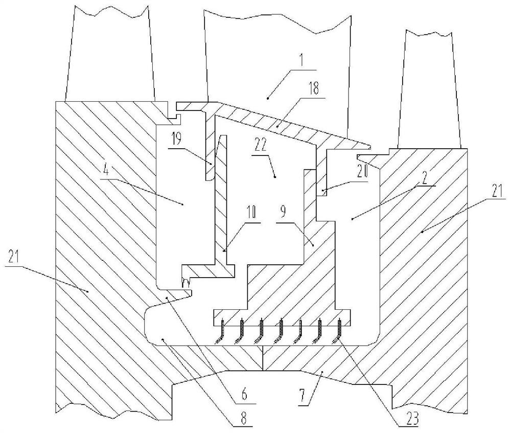
[0081] The following embodiment shows that the left half of the turbine interstage seal structure of the present invention includes 3 working sections with the same height, the right half includes 7 working sections, the left half and the right half are respectively connected to the vane by bolts The upstream extension end of the inner shroud is connected with the downstream extension end of the stator inner shroud, and the right half of the working section is fixed to the right half of the connecting section by punching and riveting.

[0082] The present invention provides an interstage seal structure of a gas turbine turbine, in which a disc seal extension end 6 and a disc extension wing 7 are processed on the rotor disc 21, including:

[0083] The turbine interstage seal structure includes a left half 10 and a right half 9, the left half 10 and the right half 9 are split structures that are not connected;

[0084] The left half part 10 of the turbine interstage seal structu...

Embodiment 2

[0104] The following embodiment shows that the left half of the turbine interstage seal structure of the present invention includes 2 working sections with different heights, the right half includes 10 working sections, the left half and the right half are respectively connected to the vane by bolts The upstream extension end of the inner shroud is connected with the downstream extension end of the inner shroud of the stator vane, and the right half of the working section is fixed to the right half of the connecting section by locking block assembly.

[0105] The present invention provides an interstage seal structure of a gas turbine turbine, in which a disc seal extension end 6 and a disc extension wing 7 are processed on the rotor disc 21, including:

[0106] The turbine interstage seal structure includes a left half 10 and a right half 9, the left half 10 and the right half 9 are split structures that are not connected;

[0107] The left half part 10 of the turbine interst...


PUM


Abstract

The invention provides an interstage sealing structure of a gas turbine turbine, which belongs to the field of mechanical structure design. The disc seal extension end and extension wing are processed on the rotor disc. The interstage seal structure is composed of unconnected left and right parts, which are respectively installed on the inner shroud of the stator blade and on the downstream extension end. The left half is directly The sealing teeth are processed to form a seal with the extended end of the wheel seal. The sealing teeth on the left half are two or more teeth, which increases the gap between the tops of the sealing teeth and reduces the dynamic and static friction during operation. The sealing teeth are as close as possible to the intake side to avoid seal failure during unit operation. The right half is installed at the downstream extension end of the inner shroud of the stator vane, and the sealing teeth with a bending angle are installed on the connecting section. The sealing teeth are processed by elastic materials and form a seal with the rotor disc protruding wings. During grinding, the irreversible damage to the sealing teeth is prevented by its own elastic deformation, and the damage to the rotating parts is weakened.

Description

technical field [0001] The invention relates to the field of mechanical structure design, in particular to an interstage sealing structure of a gas turbine turbine. Background technique [0002] In a gas turbine, the working temperature of the rotor disk is relatively high. If the temperature is not controlled, the excessively high temperature will lead to a decrease in strength, which will affect the safe operation of the unit. The usual method is to introduce cooling air to cool the wheel disk. The cooling air is generally supplied from the air supply chamber at the outer belt of the stator blade, flows through the inner channel of the stator blade, and enters the inner shroud of the stator blade and the interstage seal ring. Finally, the upstream disc and the downstream disc are cooled respectively after the upstream seal and the downstream seal. The gas after cooling the disc will flow into the main flow through the gap between the rotor surface and the stator surface, a...

Claims


Application Information

Patent Timeline
Patent Type & Authority Patents(China)
IPC IPC(8): F01D11/00
CPCF01D11/001
Inventor 潘慧斌蓝吉兵张发生张伟赵旭洋隋永枫辛小鹏赵鸿琛
Owner 浙江燃创透平机械有限公司
Why Eureka
Try Eureka