Mode Switching Based Strong Offset Resistance Wireless Power Transfer System
A wireless power transmission, anti-offset technology, applied in the direction of converting AC power input to DC power output, electrical components, circuit devices, etc., can solve the problems of large size, high cost and low efficiency of DC/DC converters
- Summary
- Abstract
- Description
- Claims
- Application Information
AI Technical Summary
Problems solved by technology
Method used
Image
Examples
specific Embodiment approach 1
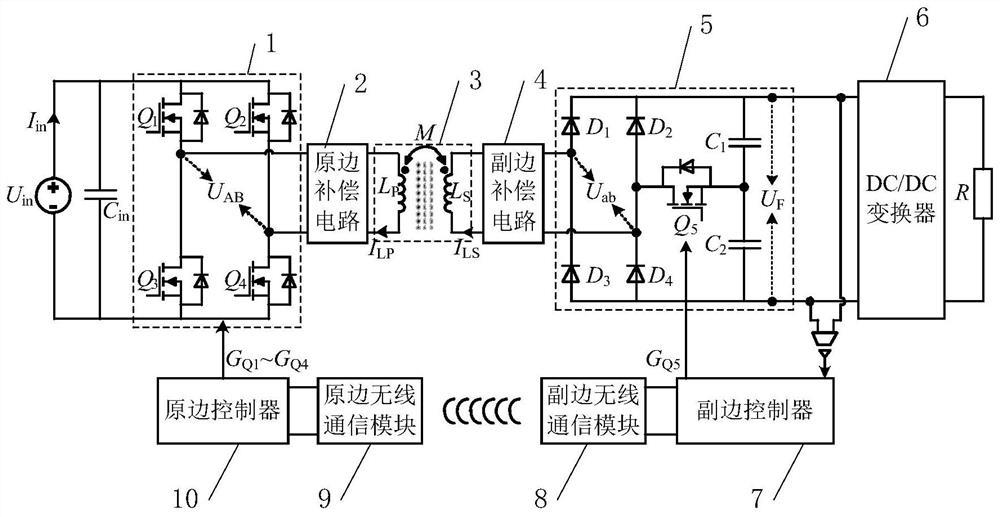
[0053] Specific embodiment one: the following combination figure 1 This embodiment will be described. The strong anti-offset wireless power transmission system based on mode switching described in this embodiment includes an inverter switching circuit 1, a primary side compensation circuit 2, a loosely coupled transformer 3, a secondary side compensation circuit 4, and a rectifier switching circuit. circuit 5, DC / DC converter 6, primary side controller 10, primary side wireless communication module 9, secondary side controller 7 and secondary side wireless communication module 8;
[0054] The power input terminal of the inverter switching circuit 1 is connected to the source U in ; The signal output end of the inverter switching circuit 1 is connected to the signal input end of the primary side compensation circuit 2, and the signal output end of the primary side compensation circuit 2 is connected to the primary side self-inductance coil L of the loosely coupled transformer 3...
specific Embodiment
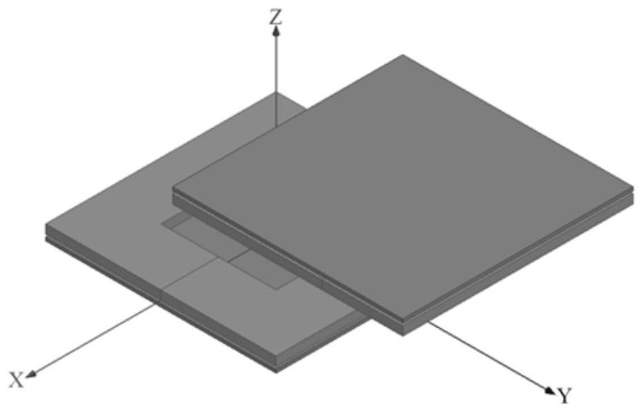
[0094] The coupling mechanism adopts such as figure 2 The plane square coil shown, the outer dimension of the unilateral coupling mechanism is 200×200×8mm 3 , the internal square hole size is 80×80mm 2 , the rated transmission distance is 50mm.
[0095] figure 2 The change curve of the coupling coefficient of the shown coupling mechanism with the offset vector M is as follows Figures 5(a) to 5(c) As shown, the offset process is briefly described as follows: at the beginning, the secondary coil is facing the primary coil, the transmission distance is equal to the rated value (50mm), and the coupling coefficient k=0.378 at this time; in Figure 5(a), the secondary coil Offset along the Z axis by 20mm, that is, M changes from (0,0,0) to (0,0,20), and the coupling coefficient decreases from 0.378 to 0.262; in Figure 5(b), the secondary coil is offset in the aforementioned Z axis. On the basis of the shift, continue to shift 40mm along the Y axis, that is, M changes from (0,0...
PUM
 Abstract
Description
Claims
Application Information
 - R&D
- Intellectual Property
- Life Sciences
- Materials
- Tech Scout
- Unparalleled Data Quality
- Higher Quality Content
- 60% Fewer Hallucinations
Browse by: Latest US Patents, China's latest patents, Technical Efficacy Thesaurus, Application Domain, Technology Topic, Popular Technical Reports.
© 2025 PatSnap. All rights reserved.Legal|Privacy policy|Modern Slavery Act Transparency Statement|Sitemap|About US| Contact US: help@patsnap.com


