A low-temperature preheating system for power battery packs for new energy vehicles
A technology for power battery packs and new energy vehicles, applied in secondary batteries, circuits, electrical components, etc., can solve problems such as low preheating efficiency, and achieve high preheating heating efficiency, good preheating effect, and improved drainage effect. Effect
- Summary
- Abstract
- Description
- Claims
- Application Information
AI Technical Summary
Problems solved by technology
Method used
Image
Examples
Embodiment 1
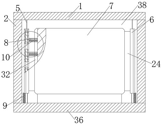
[0028] see figure 1 and Figure 4 , an embodiment provided by the present invention: a low-temperature preheating system for power battery packs for new energy vehicles, including a side plate 2, a cover plate 1 and a bottom plate 36 are connected to the side plate 2, the cover plate 1, the side plate 2 and the The bottom plate 36 is provided with a pipe port 3, and after the cover plate 1, the side plate 2 and the bottom plate 36 are assembled, a storage tank 38 is formed inside for placing the battery pack 7, and the battery pack 7 is provided with a second T-shaped slot 32, the second T A sponge 8 is slid in the shaped groove 32, and an adjustment component is connected to the sponge 8. The adjustment component pulls the sponge 8 to slide in the second T-shaped groove 32 for absorbing the water droplets 33 attached to the outer wall of the battery pack 7 when the heat and cold alternate.
[0029] In this embodiment: when using the heating device to heat water, the water fl...
Embodiment 2
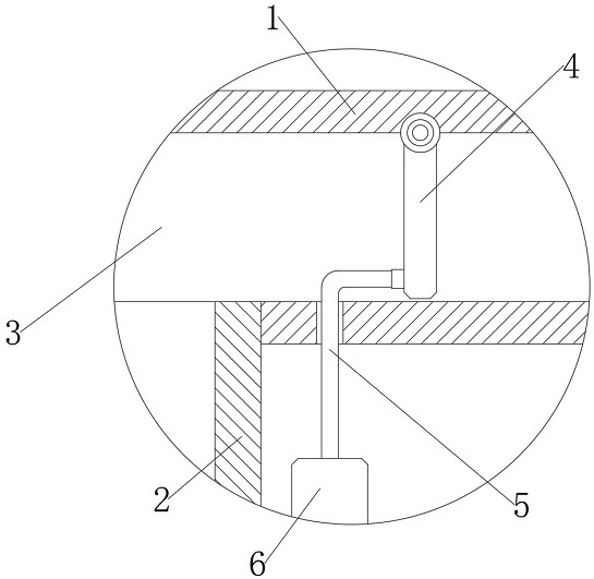
[0031] This embodiment is an improvement made on the basis of Embodiment 1, see Figure 1 to Figure 4 , the adjustment component includes a processing plate 6, the processing plate 6 slides on the inner wall of the side plate 2, a second through hole 23 is opened on one side of the processing plate 6, a first one-way valve 4 is arranged in the pipe port 3, the first one-way The valve 4 is connected to the processing plate 6 through the steel cable 5, and the first one-way valve 4 is opened by the pressure of the water flow in the pipe port 3 to carry out the water circulation, and the rotation and swing of the first one-way valve 4 is used to pull the processing plate 6 to move up and down to drive the sponge 8 Move up and down to absorb the water droplets 33 attached to the outer wall of the battery pack 7 when the battery pack 7 alternates between cold and heat.
[0032] In this embodiment: the first one-way valve 4 is arranged in the pipeline mouth 3, when the water flow in...
Embodiment 3
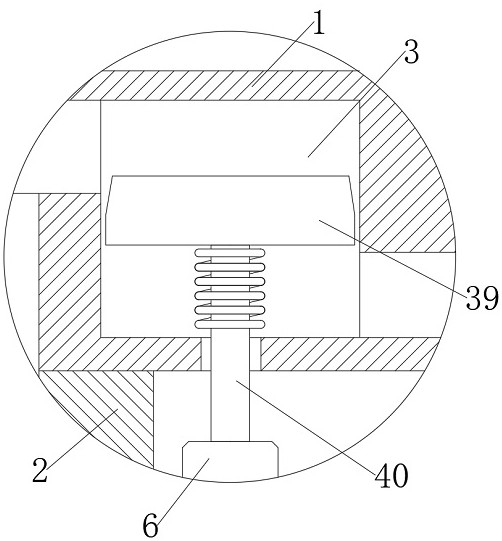
[0034] This embodiment is an improvement made on the basis of Embodiment 1, specifically refer to Figure 1 to Figure 6, the regulating part includes a processing plate 6, the processing plate 6 slides on the inner wall of the side plate 2, a second through hole 23 is opened on one side of the processing plate 6, and a pressure relief valve 39 is arranged in the pipe port 3, The pressure relief valve 39 is connected to the processing plate 6 through a connecting rod 40. When the water flow pressure in the pipe port 3 pushes the pressure relief valve 39 to carry out water circulation, the axial movement of the pressure relief valve 39 pulls the processing plate 6 to move up and down. The sponge 8 is driven to absorb the water droplets 33 attached to the outer wall of the battery pack 7 during the alternation of cold and heat.
[0035] In this embodiment: a pressure relief valve 39 is provided in the pipe mouth 3. When the water flow in the pipe mouth 3 circulates, the water flo...
PUM
 Abstract
Description
Claims
Application Information
 - R&D
- Intellectual Property
- Life Sciences
- Materials
- Tech Scout
- Unparalleled Data Quality
- Higher Quality Content
- 60% Fewer Hallucinations
Browse by: Latest US Patents, China's latest patents, Technical Efficacy Thesaurus, Application Domain, Technology Topic, Popular Technical Reports.
© 2025 PatSnap. All rights reserved.Legal|Privacy policy|Modern Slavery Act Transparency Statement|Sitemap|About US| Contact US: help@patsnap.com


