
Three-dimensional crystal plasticity finite element modeling method and system for crystal material part

A technology of crystal material and crystal plasticity, which is applied in the field of finite element model modeling, can solve the problems of inaccurate and large differences in finite element simulation results of crystal plasticity, and achieve the effect of saving sample preparation costs and testing costs

Active Publication Date: 2021-06-18
SHANDONG UNIV
View PDF5 Cites 3 Cited by
  • Summary
  • Abstract
  • Description
  • Claims
  • Application Information

AI Technical Summary

Problems solved by technology

[0006] In view of the fact that the actual microstructure of the material and the geometric elements of the part are not fully considered in the prior art, resulting in a large difference between the established grain-scale microstructure model of the crystal material part and the actual situation, and the inaccurate results of the finite element simulation of crystal plasticity, this paper The invention proposes a finite element modeling method for 3D crystal plasticity of crystal material parts that combines the real microstructure and geometric elements of the part, which can fully consider the statistical information of the 3D grain-scale microstructure of the material and the geometric elements of the part, and establish high-quality crystal plasticity. Finite element simulation model, which greatly improves the simulation accuracy

Method used


Image

  • Three-dimensional crystal plasticity finite element modeling method and system for crystal material part
  • Three-dimensional crystal plasticity finite element modeling method and system for crystal material part
  • Three-dimensional crystal plasticity finite element modeling method and system for crystal material part

Examples


Embodiment 1

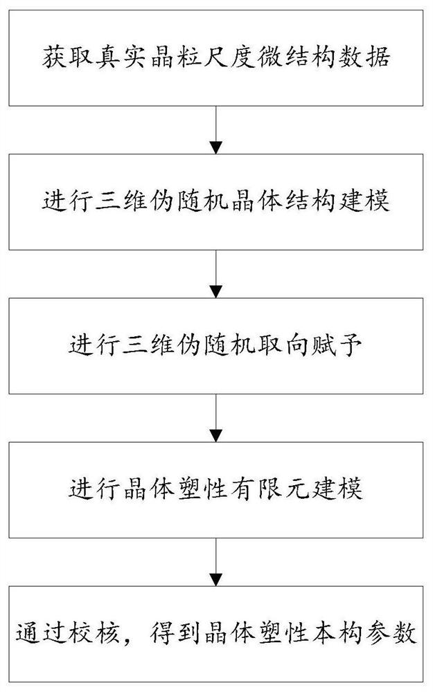
[0057] This embodiment provides a three-dimensional crystal plastic finite element modeling method for crystal material parts;

[0058] Such as figure 1 As shown, the three-dimensional crystal plastic finite element modeling method of crystal material parts includes:

[0059] S101: The obtained data includes grain size data, orientation data and grain boundary misorientation data of real crystal material parts, and distribution curves are drawn respectively according to the obtained data to obtain the distribution law of the grain size data and the distribution law of the orientation data. The distribution law and the distribution law of the misorientation data of the grain boundary;

[0060] S102: According to the acquired grain size data distribution law, iteratively generate grain size data for the minimum oriented bounding box of the crystal material part model; calculate each The seed point coordinates of the grains; based on the seed point coordinates of each grain, th...

Embodiment 2

[0186] This embodiment provides a three-dimensional crystal plastic finite element modeling system for crystal material parts;

[0187] 3D crystal plastic finite element modeling system for crystal material parts, including:

[0188]The data acquisition module is configured to: the acquired data includes grain size data, orientation data and grain boundary misorientation data of real crystal material parts, and draws distribution curves respectively according to the acquired data to obtain grain size data The distribution law of the orientation data, the distribution law of the orientation data and the distribution law of the misorientation data of the grain boundary;

[0189] The microstructure building block is configured to: iteratively generate grain size data for the minimum oriented bounding box of the crystal material part model through the acquired grain size data distribution law; Based on the grain size data, the seed point coordinates of each grain are calculated; ...

Embodiment 3

[0197] This embodiment also provides an electronic device, including: one or more processors, one or more memories, and one or more computer programs; wherein, the processor is connected to the memory, and the one or more computer programs are programmed Stored in the memory, when the electronic device is running, the processor executes one or more computer programs stored in the memory, so that the electronic device executes the method described in Embodiment 1 above.

[0198] It should be understood that in this embodiment, the processor can be a central processing unit CPU, and the processor can also be other general-purpose processors, digital signal processors DSP, application specific integrated circuits ASIC, off-the-shelf programmable gate array FPGA or other programmable logic devices , discrete gate or transistor logic devices, discrete hardware components, etc. A general-purpose processor may be a microprocessor, or the processor may be any conventional processor, o...


PUM


Abstract

The invention discloses a three-dimensional crystal plasticity finite element modeling method and system for a crystal material part. The method comprises the steps of obtaining the data of a real crystal material part, and obtaining a distribution rule according to the obtained data, generating grain size data for the minimum directional bounding box of the crystal material part model through the obtained grain size data distribution rule, generating a grain size model of the minimum directional bounding box, removing redundancy of the grain size model to obtain a three-dimensional pseudo-random grain size microstructure of the crystal material part, iteratively giving orientation to each grain in the three-dimensional pseudo-random grain scale microstructure through the obtained grain orientation data distribution rule and the obtained crystal boundary orientation difference data distribution rule, constructing a crystal plasticity finite element model of the crystal material part through the obtained three-dimensional pseudo-random grain scale microstructure of the crystal material part and the orientation data of the grains, and realizing crystal plasticity finite element simulation. The method can be used for mechanical property simulation and service simulation.

Description

technical field [0001] The invention relates to the technical field of finite element model modeling, in particular to a three-dimensional crystal plastic finite element modeling method and system for crystal material parts. Background technique [0002] The statements in this section merely mention the background technology related to the present invention and do not necessarily constitute the prior art. [0003] There are two main problems in the existing crystal plastic finite element modeling technology of crystal material parts: [0004] The existing grain-scale microstructure modeling methods mainly include the EBSD layered slice method and the Voronoi random generation method, both of which have shortcomings. The Voronoi random generation method uses triangulation technology to randomly create a grain-scale microstructure model. This method does not consider the real grain-scale microstructure information of the material, which is quite different from the actual situ...

Claims


Application Information

Patent Timeline
IPC IPC(8): G06F30/23
CPCG06F30/23
Inventor 宋清华冀寒松蔡文通赵有乐刘战强穆尼斯·库尔玛·古普塔
Owner SHANDONG UNIV
Learn More