Eureka AIR delivers breakthrough ideas for toughest innovation challenges, trusted by R&D personnel around the world.

Regeneration system of rotary wheel dehumidification equipment and rotary wheel dehumidification equipment

A regenerative system and wheel dehumidification technology, which is applied in the field of wheel dehumidification equipment, can solve the problems of high energy consumption and achieve the effects of reducing energy consumption, reducing heating load, and increasing temperature

Pending Publication Date: 2021-06-18
EMERSON CLIMATE TECH (SUZHOU) CO LTD
View PDF0 Cites 0 Cited by
  • Summary
  • Abstract
  • Description
  • Claims
  • Application Information

AI Technical Summary

Problems solved by technology

This is because the energy consumption on the regeneration side of the rotary dehumidification equipment is still relatively large. In view of cost considerations, the heat pump device on the regeneration side of the rotary dehumidification equipment often uses a fixed-speed heat pump, and this constant-speed heat pump is still difficult. Continuous heat regulation for different regeneration temperatures for different operating conditions (e.g., different seasons)

Method used


Image

  • Regeneration system of rotary wheel dehumidification equipment and rotary wheel dehumidification equipment
  • Regeneration system of rotary wheel dehumidification equipment and rotary wheel dehumidification equipment
  • Regeneration system of rotary wheel dehumidification equipment and rotary wheel dehumidification equipment

Examples


Embodiment Construction

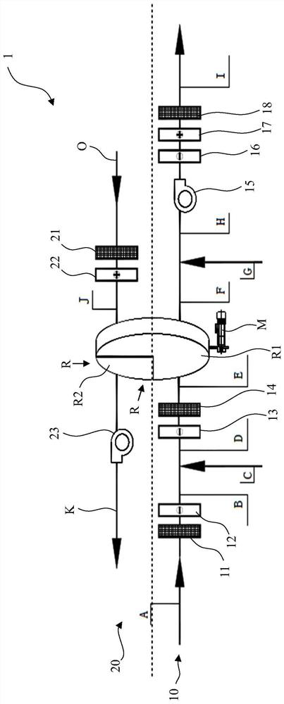
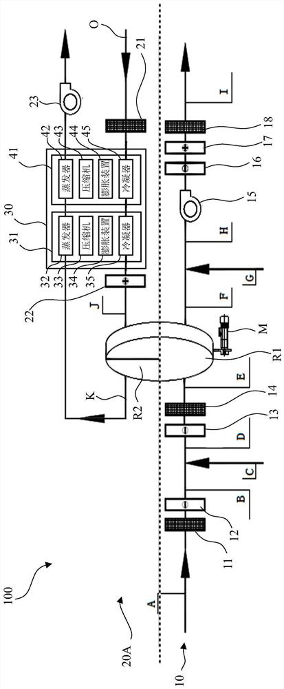
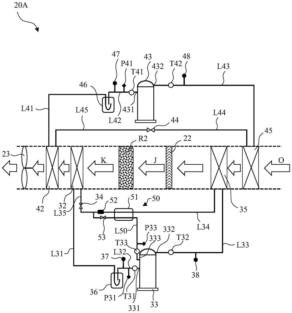
[0027] The description below is essentially exemplary and is not intended to limit the invention, application and use. It should be understood that in all of these figures, similar reference numerals indicate the same or similar parts and features. Each of the drawings only schematically represents the concept and principles of the embodiments of the present invention, and does not necessarily show specific dimensions and ratios of the various embodiments of the present invention. The specific portion of the specific drawings may be exaggerated to illustrate the related details or structures of the embodiments of the present invention.

[0028] In the description of the embodiments of the present invention, the orientation of the "upper", "lower", "left", and "right" is used is the view, lower, left, and left, and left, and left, The right position is described. In practical applications, the location relationships used in "upper", "lower", "left", "upper", and the right "are defi...


PUM


Abstract

The invention relates to a regeneration system for rotary wheel dehumidification equipment. The system comprises a regeneration fresh air inlet and a heat pump device, wherein regeneration fresh air enters the regeneration system through the regeneration fresh air inlet; the heat pump device is arranged at the downstream of the regeneration fresh air inlet. the heat pump device comprises a first heat pump unit and a second heat pump unit; and a condenser of the first heat pump unit and a condenser of the second heat pump unit are arranged in a regeneration air duct between the regeneration fresh air inlet and the regeneration area of the dehumidification rotary wheel. The invention further relates to the rotary wheel dehumidification equipment. According to the rotary wheel dehumidification equipment, by arranging the heat pump device, on one hand, the temperature of regeneration fresh air can be effectively increased, energy of exhaust air at the regeneration side can be effectively recycled, the heating load of the regeneration heating device can be reduced, and energy consumption of the regeneration system can be remarkably reduced; and on the other hand, the temperature of regeneration air can be continuously adjusted within a large range, and different working conditions can be adapted.

Description

Technical field [0001] The present invention relates to a regeneration system of a runner dehumidification device and a rotor dehumidification device having the regeneration system. Background technique [0002] The content of this section only provides background information related to the present invention, which may not constitute a prior art. [0003] Runner dehumidification techniques are industrially used dehumidification techniques. The main components of the dehumidifier apparatus for applying a runner dehumidification technique include dehumidifying wheels. The dehumidifier is sealed in partition, including the processing zone and the regeneration zone, and the rotary dehumidification apparatus is generally divided into a dehumidification process side and regenerated side based on the flow direction of the air dehumidification equipment in the wheel. The dehumidifier is driven to slowly rotate, in the dehumidifier side of the rotary dehumidification device, to be treated...

Claims


Application Information

Patent Timeline
IPC IPC(8): F24F3/14F24F12/00F24F13/30
CPCF24F3/1429F24F12/001F24F13/30F24F2003/144F24F2003/1464
Inventor 杨春束宏飞
Owner EMERSON CLIMATE TECH (SUZHOU) CO LTD
Why Eureka
Eureka Blog
Learn More