
A pulse balloon and its application

A balloon and pulse technology, applied in the field of medical devices, can solve problems such as heart rate interference, achieve the effect of improving the degree of integration, increasing the service life, and avoiding separation

Active Publication Date: 2021-08-20
SHANGHAI BIO HEART BIOLOGICAL TECHNOLOGY CO LTD
View PDF10 Cites 0 Cited by
  • Summary
  • Abstract
  • Description
  • Claims
  • Application Information

AI Technical Summary

Problems solved by technology

During the conduction of high-voltage electricity through the electrolyte, part of the high-voltage electricity will break down the thin wall, and part of the high-voltage electricity will appear on the outermost side of the balloon. The high-voltage electricity will act on the patient's blood vessels and cause heart rate disturbance.

Method used


Image

  • A pulse balloon and its application
  • A pulse balloon and its application
  • A pulse balloon and its application

Examples


Embodiment 1

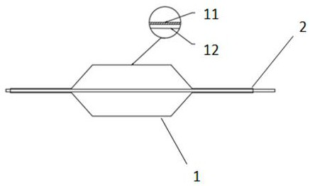
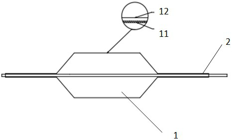
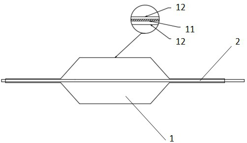
[0058] Such as figure 1 As shown, the present embodiment provides a pulse balloon, which includes a balloon body 1 and an inner tube 2; the inner tube 2 runs through the balloon body 1; the inner tube 2 is located symmetrically on the balloon body 1 On the axis; electrodes are arranged on the inner tube 2; the balloon body includes an insulating layer 11 and a balloon wall 12 from the outside to the inside; the thickness of the balloon wall is 20 μm, and the thickness of the insulating layer is 3 μm; The material of the balloon wall is polyethyleneimine, and the material of the insulating layer is polytetrafluoroethylene.

Embodiment 2

[0060] Such as figure 1 As shown, the present embodiment provides a pulse balloon, which includes a balloon body 1 and an inner tube 2; the inner tube 2 runs through the balloon body 1; the inner tube 2 is located symmetrically on the balloon body 1 on the shaft; electrodes are arranged on the inner tube 2; the balloon body includes an insulating layer 11 and a balloon wall 12 from the outside to the inside; the balloon body 1 is prepared by spraying; the balloon wall The thickness is 15 μm, and the thickness of the insulating layer is 4 μm; the material of the balloon wall is polyethyleneimine, and the material of the insulating layer is polytetrafluoroethylene.

[0061] The spraying includes: after the balloon wall is blow-molded, the polytetrafluoroethylene dispersion is sprayed on the outer surface of the balloon wall, and dried at 190°C. When the balloon pressure reaches 14ATM, set the pulse voltage at 5000V and 1HZ to start discharging 100 times. After repeating 5 times...

Embodiment 3

[0063] Such as figure 1 As shown, the present embodiment provides a pulse balloon, which includes a balloon body 1 and an inner tube 2; the inner tube 2 runs through the balloon body 1; the inner tube 2 is located symmetrically on the balloon body 1 on the shaft; the inner tube 2 is provided with electrodes; the balloon body includes an insulating layer 11 and a balloon wall 12 from the outside to the inside; the balloon body 1 is prepared by blow molding; the balloon The thickness of the wall is 25 μm, and the thickness of the insulating layer is 2 μm; the material of the balloon wall is polyethyleneimine, and the material of the insulating layer is polytetrafluoroethylene.

[0064] The package blow molding includes: putting the PTFE film on the outer layer of the balloon tube, putting it into the mold of the balloon molding machine, and performing blow molding. The process parameters of the blow molding are: the blow molding temperature is 140°C, heating The time is 15s, th...


PUM

PropertyMeasurementUnit
thicknessaaaaaaaaaa
thicknessaaaaaaaaaa
thicknessaaaaaaaaaa

Abstract

The invention relates to the field of medical devices, and more specifically, the invention relates to a pulse balloon and its application. The impulse balloon includes a balloon body and an inner tube; the balloon body includes an insulating layer and a balloon wall. An insulating layer is set on the balloon body. When the balloon is working, the balloon body is filled with electrolyte, so that the electrodes emit high-pulse piezoelectricity to generate pulses, and the balloon vibrates along with the propagation of the electrolyte, so that most of the electric energy is converted into The mechanical energy breaks down the calcified area of ​​the blood vessel, and the residual high voltage is blocked by the insulating layer, which avoids the conduction of the high voltage on the surface of the balloon and limits the excess high voltage at the pulse source. The use of the balloon body with an insulating layer can prevent excess electricity from being conducted to the pacemaker, signal conduction area, etc., so that the patient's heart rate can be maintained in a relatively stable state. For patients with severe calcification, the discharge voltage and discharge frequency can be increased to avoid damage to the human body while improving the effectiveness of the operation.

Description

technical field [0001] The invention relates to the field of medical devices, and more specifically, the invention relates to a pulse balloon and its application. Background technique [0002] Aortic calcification, also called aortic sclerosis, is the buildup of calcium deposits on the aortic valve in the heart. This often results in a heart murmur, which can be easily heard with a stethoscope placed over the heart. However, aortic calcification usually does not significantly affect aortic valve function. But in some cases, calcium deposits thicken and narrow the opening in the aortic valve. This reduces blood flow through the valve, causing chest pain or a heart attack. This narrowing is called aortic stenosis. [0003] The current method for reducing calcification is to apply shock waves to the calcified area of ​​the valve to promote cracking and / or break up the calcium deposits, thereby softening and / or loosening and / or removing the calcium deposits that have hardened...

Claims


Application Information

Patent Timeline
Patent Type & Authority Patents(China)
IPC IPC(8): A61B17/22B29C49/78B29C49/04
CPCA61B17/22004A61B17/22022B29C49/78B29C49/04A61B2017/22051A61B2017/22065A61B2017/22062A61B17/22012A61B2017/22025A61B2017/00526A61B2017/00929B29D22/02A61M25/1029A61M2025/1075A61B2017/00778
Inventor 汪立张晨朝梁鑫峰蔡涛王君毅
Owner SHANGHAI BIO HEART BIOLOGICAL TECHNOLOGY CO LTD
Learn More