
High-temperature-resistant dry-type capacitor

A capacitor and high temperature resistant technology, applied in the field of capacitors, can solve problems such as dry capacitor damage, stability impact, accidents, etc.

Inactive Publication Date: 2021-06-11
重庆海石物流运输有限公司
View PDF0 Cites 0 Cited by
  • Summary
  • Abstract
  • Description
  • Claims
  • Application Information

AI Technical Summary

Problems solved by technology

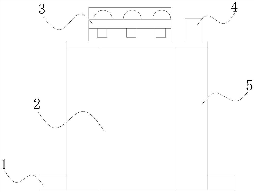
[0003] When using dry capacitors, since there are multiple layers of insulating fillers inside the dry capacitors, they cannot spread outwards, so that the heat generated inside the capacitors will directly accumulate inside the capacitors. Excessive heat will cause the capacitors to burn due to heat. The generation of water vapor will easily cause moisture damage to internal components, affect the stability during use, and cause damage to dry capacitors, and the bottom of the capacitor will be exposed to the outside, which will easily cause abnormal leakage during use, causing unnecessary accidents and reducing The safety of using capacitors

Method used


Image

  • High-temperature-resistant dry-type capacitor
  • High-temperature-resistant dry-type capacitor
  • High-temperature-resistant dry-type capacitor

Examples


Embodiment 1

[0031] see figure 1 , the present invention provides a technical solution: a high temperature resistant dry capacitor, its structure includes a base 1, a capacitor core 2, an electrode 3, a body 4, and a protective device 5, the base 1 is installed on the protective device 5, the The protection device 5 is provided with a main body 4 connected thereto, and the main body 4 is provided with a capacitor core 2 inside, and the capacitor core 2 is electrically connected to the electrode 3 .

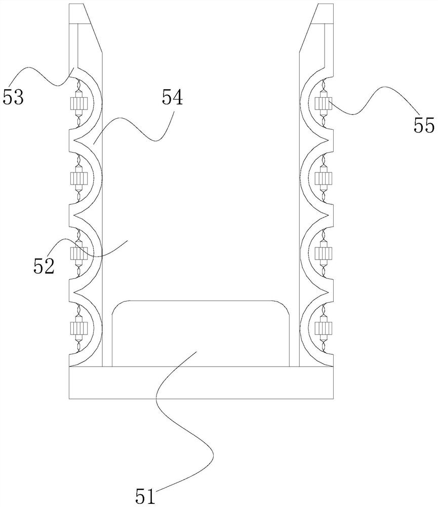
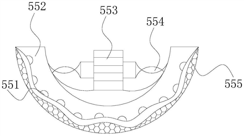
[0032] see figure 2 , the protective device 5 includes a limiting component 51, a placement cavity 52, a connecting plate 53, a guide 54, and a dehumidifying component 55. Both sides of the limiting component 51 are provided with guides 54 connected thereto. The guide 54 is in communication with the connection plate 53, and the end of the connection plate 53 away from the guide 54 is fastened to the dehumidification assembly 55. There are eight dehumidification assemblies 55, and the eight ...

Embodiment 2

[0042] see figure 1 , the present invention provides a technical solution: a high temperature resistant dry capacitor, its structure includes a base 1, a capacitor core 2, an electrode 3, a body 4, and a protective device 5, the base 1 is installed on the protective device 5, the The protection device 5 is provided with a main body 4 connected thereto, and the main body 4 is provided with a capacitor core 2 inside, and the capacitor core 2 is electrically connected to the electrode 3 .

[0043] see figure 2 , the protective device 5 includes a limiting component 51, a placement cavity 52, a connecting plate 53, a guide 54, and a dehumidifying component 55. Both sides of the limiting component 51 are provided with guides 54 connected thereto. The guide 54 is in communication with the connection plate 53, and the end of the connection plate 53 away from the guide 54 is fastened to the dehumidification assembly 55. There are eight dehumidification assemblies 55, and the eight ...


PUM


Abstract

The invention discloses a high-temperature-resistant dry-type capacitor which structurally comprises a base, a capacitor core, an electrode, a body and a protection device. When the high-temperature-resistant dry-type capacitor is used, the body is fixedly clamped on an opening and closing arm through the cooperation of a rubber cushion and a friction plate, so that the opening and closing arm can protect the bottom of the body, and the bottom of the body is prevented from being exposed outside. An adsorption sheet and a packing layer are matched with water vapor in a gas for adsorption and drying treatment, the treated hot gas can be mixed with the external air under the action of a rotating sheet, so that the temperature of the hot gas is effectively reduced, parts in the body are prevented from being damaged due to the influence of the water vapor, and the stability and the use safety of the dry-type capacitor during use are ensured.

Description

technical field [0001] The invention relates to the field of capacitors, in particular to a high temperature resistant dry capacitor. Background technique [0002] A capacitor is composed of two electrodes and a dielectric material between them. It is usually referred to as capacitance for its ability to hold charges. It is represented by the letter C. The capacitor is one of the electronic components widely used in electronic equipment. The capacitor is protected by protective components to prevent There are unnecessary accidents in capacitors. When using dry capacitors, what needs to be improved: [0003] When using dry capacitors, since there are multiple layers of insulating fillers inside the dry capacitors, they cannot spread outwards, so that the heat generated inside the capacitors will directly accumulate inside the capacitors. Excessive heat will cause the capacitors to burn due to heat. The generation of water vapor will easily cause moisture damage to internal c...

Claims


Application Information

Patent Timeline
Patent Type & Authority Applications(China)
IPC IPC(8): H01G2/08H01G2/10H01G4/002H01G4/224
CPCH01G2/08H01G2/10H01G4/002H01G4/224
Inventor 王燕
Owner 重庆海石物流运输有限公司
Learn More