
High-efficiency drying equipment for graphene production and drying method

A drying equipment and high-efficiency technology, which is applied in drying, drying machines, lighting and heating equipment, etc., can solve the problems affecting the drying effect of draining effect, so as to improve the drying effect, increase contact, and speed up draining speed effect

Active Publication Date: 2021-06-11
福建烯望新材料科技有限公司
View PDF5 Cites 2 Cited by
  • Summary
  • Abstract
  • Description
  • Claims
  • Application Information

AI Technical Summary

Problems solved by technology

[0010] In the process of using graphene materials for production and processing, it is usually necessary to dry graphene materials or materials processed from graphene; the existing drying equipment is to put the materials to be dried inside the drying box , drying by hot air. In order to improve the drying effect, the cylinder will be used to place the material, and the draining will be accelerated by rotation, which is convenient for drying. However, the structure for placing the material is usually provided with holes. When the cylinder is rotated to drain, The drained water will fall on the adjacent cylinder, affecting the draining effect and the subsequent drying effect

Method used


Image

  • High-efficiency drying equipment for graphene production and drying method
  • High-efficiency drying equipment for graphene production and drying method
  • High-efficiency drying equipment for graphene production and drying method

Examples


Embodiment 1

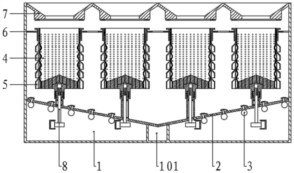
[0058] Please refer to the drawings, the present invention provides a technical solution: a highly efficient drying apparatus for graphene production, including a drying tank 1, and a feed plate 7, a feed plate 7, a feed A positioning plate 6 is provided below the plate 7, and the bottom portion of the drying box 1 is fixed, and a plurality of material placement mechanisms are uniformly provided between the conductive plate 2 and the positioning plate 6, and the conductive plate 2 is provided. There is a drying assembly, and the bottom of the dryer 1 is provided with a drive assembly, and the material placement mechanism corresponds to the drive assembly, and the two sides of the conductive plate 2 are symmetrically inclined, and the intermediate is higher than that of both sides, which is easy to dry after drying The material is concentrated in the middle of the conductive plate 2 for the lower material, and the central portion of the conductive plate 2 is uniformly provided with...

Embodiment 2

[0066] The structure of the present embodiment is substantially identical to the examples, and the feed plate 7 is evenly provided with a plurality of stroke feed grooves 701 along the rectangular array, and the feed groove 701 is provided with a feed. The mouth 702, and the bottom surface of the feed plate 7 has an annular third electromagnet 703 on the outer side of the pumping port 702, the third electromagnet 703 is electrically connected to the power source and switch, and the positioning plate 6 includes a plurality of positioning rings that are uniformly set. 601. The positioning ring 601 corresponds to the position of the feed cell 701, and the adjacent two positioning ring 601 are fixedly connected by the fixed lever 602, and the positioning ring 601 located outside is passed through the side of the fixed rod 602 and the side of the drying box 1. The wall fixing is connected, and the positioning ring 601 is rotated and connected to the positioning cartridge 603, and there...

Embodiment 3

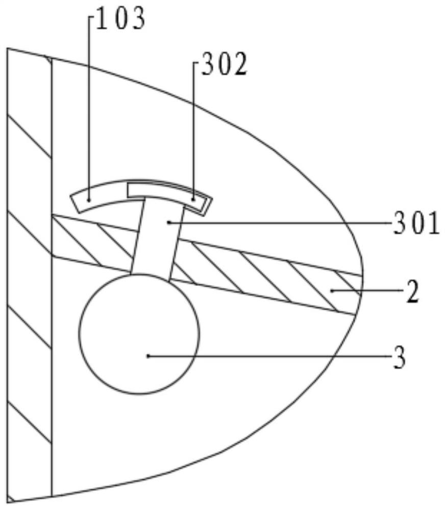
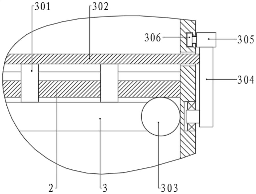
[0079] The structure of the present embodiment is substantially identical to the second embodiment, and the distinction is that the top end of the exhaust pipe 301 is set to a curved shape, and a curved seal is provided with a top of the outlet pipe 301 on the same dry tube 3. The plate 302, and the bottom curve surface of the sealing plate 302 slides to the top arc surface of the outlet tube 301, and there is a curved groove 103 on both sides of the drying box 1, and both ends of the sealing plate 302 are slidably connected to the arc. The groove 103, and one end projects out of the drying tank 1, and fixes the center of the sector plate 304, the center sealing plate 302 of the sector plate 304, and the arc-shaped top surface of the sector plate 304 is uniformly fixed in the arc direction. A plurality of sector plates 304 located on the same side are in the same first rack 305 by the tooth teeth, and the first rack 305 is the same as the tilt angle of the corresponding side of th...


PUM


Abstract

The invention discloses high-efficiency drying equipment for graphene production and a drying method in the technical field of graphene production. The high-efficiency drying equipment comprises a drying box, wherein feeding plates, positioning plates and a material guide plate are sequentially arranged in an inner cavity of the drying box from top to bottom; a plurality of material placing mechanisms are evenly arranged between the material guide plate and the positioning plates; a driving assembly is connected to the bottom of each material placing mechanism; and a drying assembly is arranged on the material guide plate. According to the high-efficiency drying equipment and the drying method, materials are drained through draining barrels, the draining speed is increased through the centrifugal effect during rotation, and drained water cannot be thrown into the adjacent draining barrels through the effect of annular baffles; and under the action of a first electromagnet and adsorption plates in connecting cylinders, water retaining cylinders move downwards, dewatering tanks and the concave positions of the draining barrels are staggered, then drying is carried out through the drying assembly, after drying is finished, the draining barrels move upwards, the bottom ends of the draining barrels are separated from sealing tables, and the materials move outwards along the top surfaces of the sealing tables and fall onto the material guide plate.

Description

Technical field [0001] The present invention relates to the technical field of graphene production, and is specifically used for high-efficiency drying equipment and drying methods for graphene production. Background technique [0002] Graphene is a SP by carbon atom 2 Hybrid tracks form a two-dimensional carbon nanoma with a hexagonal lattice. [0003] Grainne is one of the most known intensity, but also has a good toughness, and can be bent, the theoretical Young's modulus of graphene reaches 1.0 TPa, and inherent tensile strength is 130 gpa. Reduction graphene modified by hydrogen plasma has a very good strength, and the average modulus can be 0.25TPa. [0004] The graphite paper composed of graphene flakes has a lot of holes, so the graphite paper is very brittle, however, the oxidation of functionalized graphene is obtained, and the functionalized graphene is made into a graphite paper will be very strong. [0005] Due to high conductivity, high strength, ultra-thin characte...

Claims


Application Information

Patent Timeline
IPC IPC(8): F26B11/18F26B5/08F26B21/00F26B25/00F26B25/18
CPCF26B11/18F26B5/08F26B25/002F26B25/18F26B25/00F26B21/001F26B21/004
Inventor 万东
Owner 福建烯望新材料科技有限公司
Learn More