
Embankment reinforcing system for liquefiable site reinforced gravel pile composite foundation and reinforcing method

A technology for composite foundations and liquefaction sites, applied in sheet pile walls, foundation structure engineering, buildings, etc., can solve problems such as the lack of liquefiable sand foundations, achieve improved stability and anti-liquefaction ability, strong anti-liquefaction ability, and overall good sex effect

Inactive Publication Date: 2021-06-08
WUHAN UNIV
View PDF5 Cites 2 Cited by
  • Summary
  • Abstract
  • Description
  • Claims
  • Application Information

AI Technical Summary

Problems solved by technology

Reinforced crushed stone pile technology is a foundation treatment technology developed on the basis of crushed stone pile technology. By wrapping reinforcement materials around the crushed stone pile, the lateral restraint of the pile body is significantly improved, and the pile is further improved. The stiffness and bearing capacity of the body, most of the existing designs consider its application in soft soil foundations, but it is relatively scarce in liquefiable sandy soil foundations

Method used


Image

  • Embankment reinforcing system for liquefiable site reinforced gravel pile composite foundation and reinforcing method
  • Embankment reinforcing system for liquefiable site reinforced gravel pile composite foundation and reinforcing method
  • Embankment reinforcing system for liquefiable site reinforced gravel pile composite foundation and reinforcing method

Examples


Embodiment 1

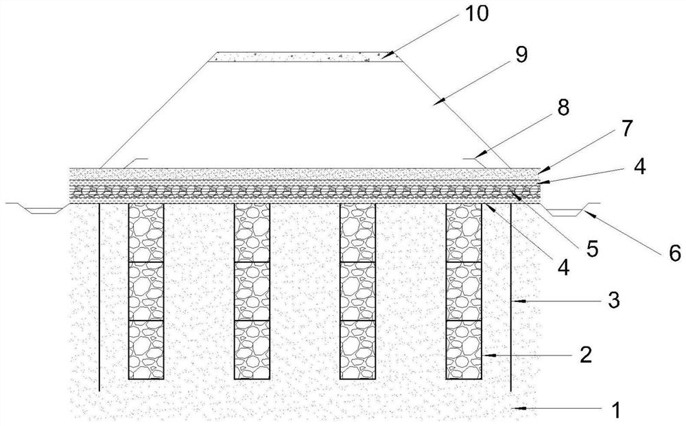
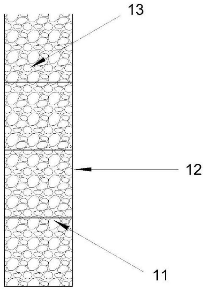
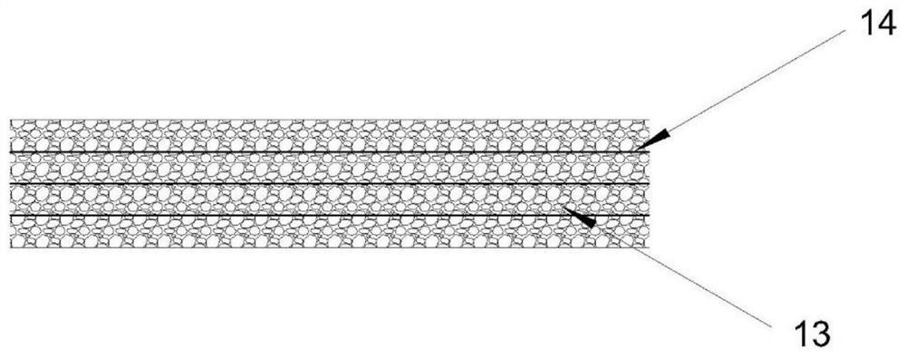
[0051] Such as Figure 1 ~ 4 As shown, a liquefied field plus damper pile composite ground base path embankment reinforcement system, including two-way plug-in gravel pile 2, plate pile wall 3, geotextile pad layer 4, geogr grid plus crush pad layer 5, Drainage 6, sand mat 7, embankment filling layer 9 and asphalt concrete surface layer 10. Among them, the two-way plug-in gravel pile 2, the geotextile pad layer 4, the geogr grid plus crushed pad layer 5, the geotextile pad layer 4, the sand pad layer 7 and the embankment filling layer 9 are sequentially arranged from below; The two-dimensional plug-gravel pile 2 is arranged on both sides of the plate pile wall 3. On both sides of the reinforced crumb pad, the drainage groove 6 is arranged, and a liquefied ventricular reinforcement system is formed.

[0052] The diameter of the two-way plug-gravel pile 2 is 0.8m, the length is 5m, the pile spacing is 4m and is a square distribution; the U-shaped steel plate pile 15 used by the plate...


PUM


Abstract

The invention belongs to the field of foundation reinforcing engineering, and relates to an embankment reinforcing system for liquefiable site reinforced gravel pile composite foundation and a reinforcing method. The reinforcing system involves two-way reinforced gravel piles, a sheet pile wall, a geotextile cushion layer, a geogrid reinforced gravel cushion layer, a horizontal drainage channel, drainage ditches, a sand cushion layer, an embankment filling layer and an asphalt concrete surface layer, wherein the reinforced gravel piles are constructed through a vibroflotation method and are arranged in a square shape to form a vertical drainage channel, the geotextile cushion layer, the geogrid reinforced gravel cushion layer and a second geotextile cushion layer are sequentially laid on the upper portions of the two-way reinforced gravel piles to jointly form the horizontal drainage channel, the drainage ditches are formed in the two sides of the horizontal drainage channel, the sand cushion layer is arranged at the top of the horizontal drainage channel, and finally, the embankment filling layer is built on the top surface of the sand cushion layer. The embankment reinforcing system for the liquefiable site reinforced gravel pile composite foundation and the reinforcing method are easy and convenient to construct, short in construction period, low in cost, higher in bearing capacity and liquefying resistance, the embankment reinforcing system for the liquefiable site reinforced gravel pile composite foundation and the reinforcing method which are economical and efficient are provided.

Description

Technical field [0001] The invention belongs to the field of foundation reinforcement, and more particularly to a reinforcement system and reinforcement method of a liquefied field plug-in gravel pile composite ground. Background technique [0002] my country's earthquake activity is more frequent, high strength, wide distribution, and severe earthquake. my country is close to more than 1 / 3 of the country, 1 / 2 city and more than 2 / 3 cities located 7 degrees and 7 degrees or more high intensity zone. The earthquake has caused huge disasters, especially the foundation liquefaction problems caused by the earthquake. The damage caused by seismic liquefaction mainly includes lateral flow and displacement caused by seismic liquefaction, as well as liquefied sprinkling and uneven sedimentation. [0003] Due to the low strength of the liquefied foundation (loose soil, powder, the sedimentation, the ground soil may liquefaction in the earthquake, and loss of shear strength and load capaci...

Claims


Application Information

Patent Timeline
Patent Type & Authority Applications(China)
IPC IPC(8): E02D3/00E02D3/08E02D3/10E02D5/04
CPCE02D3/00E02D3/08E02D3/10E02D5/04
Inventor 郑烨炜纪明昌王嘉鑫赵福堂
Owner WUHAN UNIV
Learn More