
Device and method for detecting microsphere defects by combining dark field imaging with space phase-shifting interference

A phase-shifting interference and dark-field imaging technology, which is applied in measuring devices, optical testing of flaws/defects, and material analysis through optical means, can solve problems such as low detection efficiency, environmental factors, and poor effectiveness

Inactive Publication Date: 2021-06-04
HARBIN INST OF TECH
View PDF5 Cites 1 Cited by
  • Summary
  • Abstract
  • Description
  • Claims
  • Application Information

AI Technical Summary

Problems solved by technology

[0005] The purpose of the present invention is to solve the problems of low detection efficiency, poor effectiveness, and the influence of environmental factors on traditional time-domain phase-shifting interferometry in existing methods for measuring micro-spherical surface defects. Ball defect detection device and method

Method used


Image

  • Device and method for detecting microsphere defects by combining dark field imaging with space phase-shifting interference
  • Device and method for detecting microsphere defects by combining dark field imaging with space phase-shifting interference
  • Device and method for detecting microsphere defects by combining dark field imaging with space phase-shifting interference

Examples


specific Embodiment approach 1

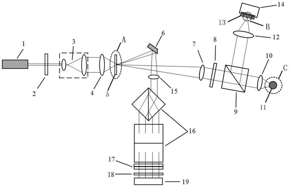
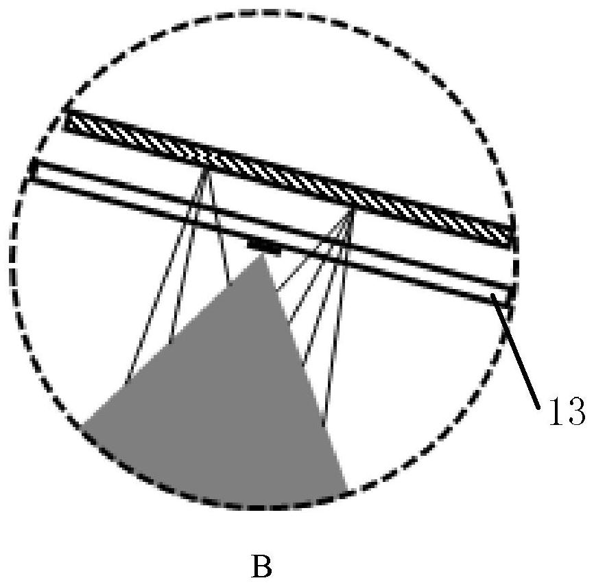
[0018] DETAILED DESCRIPTION One: Refer to Figure 1 to 6 Specifically, the present embodiment, the microsphere defect detecting device interference interference interference, including: laser 1, λ / 2 wave plate 2, 4F beam system 3, high Microscopic mirror 4, pinhole mirror 5, D-shaped mirror 6, first alignment lens 7, λ / 4 wave plate 8, spectroscopic prism 9, microscopy, imaging lens 12, mask plate 13, imaging CCD 14, a second ratio direct lens 15, a split prism group 16, a wavefront group 17, a detector 18, a large-faced high speed camera 19, and a suspension structure.

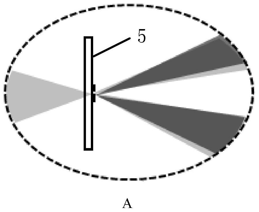
[0019] The laser 1, λ / 2 wave plate 2, 4F beam system 3, high-magnification microscope 4 and pinhole mirror 5 are sequentially arranged along the same optical axis, laser 1, λ / 2 wave plate 2, 4F beam system 3 The high-grade microscope 4 is located on the incident light direction of the pinhole mirror 5, and the laser 1 is permitted in the direction of the light surface of the pinhole mirror 5. The spectrosco...

specific Embodiment approach 2

[0029] DETAILED DESCRIPTION OF THE INVENTION 2: The microsphere defect detection method of the dark field imaging binding spatial shift interference interference is implemented based on the following device, including: λ / 2 wave plate 2, 4F beam system 3, high multiplier display Microscope 4, pinhole mirror 5, D-shaped mirror 6, first aligned straight lens 7, λ / 4 wave plate 8, spectroscopic prism 9, microscopy objective, imaging lens 12, mask plate 13, imaging CCD14 , The second ratio direct lens 15, the spectroscopic prism group 16, the wavefill set 17, the detector 18, and the largermost array high speed camera 19.

[0030] The linear polarizing light is sequentially transmitted through the λ / 2 wave plate 2, 4F beam system 3 and the high-enhanced microscope 4, and the light-diffracted light diffraced by the pinhole mirror 5 is D. The mirror 6 is reflected to the second ratio direct lens 15, and the reference light is constituted by the second ratio straight lens 15. The lig...


PUM

PropertyMeasurementUnit
diameteraaaaaaaaaa
diameteraaaaaaaaaa

Abstract

The invention discloses a device and method for detecting microsphere defects by combining dark field imaging with space phase-shifting interference, and relates to the technical field of optical detection. The problem of low detection efficiency is solved. Linearly polarized light sequentially penetrates through a lambda / 2 wave plate, a 4f beam expanding system and a high-power microscope objective and then enters a pinhole of a pinhole reflector, and a part of light diffracted by the pinhole reflector is reflected by a D-shaped reflector to a second collimating lens to form reference light. The rest part of the light sequentially penetrates through the first collimating lens, the lambda / 4 wave plate, the beam splitter prism and the microscope objective to enter the measured microsphere, the reflected light of the light sequentially penetrates through the microscope objective, the beam splitter prism, the imaging lens and the mask plate to enter the imaging CCD to form a two-dimensional information image of the measured microsphere, and the transmitted light of the beam splitter prism returns to the second collimating lens along the original path to be collimated to form measuring light; the reference light and the measuring light are superposed and modulated by the wave plate group, and the polarization analyzer enables the reference light and the measuring light to generate interference and then to enter the large-area-array high-speed camera to form a three-dimensional information image of the measured microsphere.

Description

Technical field [0001] The present invention belongs to the technical field of optical detection space object surface 3D information. Background technique [0002] The micro spheroid is one of the most commonly used component morphology, is widely used in many areas such as aerospace, military, industry, and medical care. Micro-pall surface accuracy has a vital impact on its performance. [0003] Traditional detection means, such as atomic force microscopy, although there is a high longitudinal measurement accuracy, only when a single measurement range is very small, and the overall three-dimensional shape measurement can be achieved when a high-precision mechanical scanning movement is required. At this time, the mechanical motion error is seriously affected, and since the single-point scanning measurement is used, there is a problem of low detection efficiency, poor transverse resolution, and isolation of isolation defects. The detection range is relatively large interferometri...

Claims


Application Information

Patent Timeline
Patent Type & Authority Applications(China)
IPC IPC(8): G01N21/95
CPCG01N21/8806G01N21/951
Inventor 卢丙辉刘国栋刘炳国陈凤东庄志涛甘雨路程
Owner HARBIN INST OF TECH
Learn More