
Bridge drainage system and drainage method thereof

A drainage system and bridge technology, applied in bridges, bridge construction, bridge parts, etc., can solve the problems of simple pipelines and easy blockage of drainage pipes, and achieve the effect of avoiding blockage

Pending Publication Date: 2021-06-04
郑州市公路工程公司
View PDF0 Cites 0 Cited by
  • Summary
  • Abstract
  • Description
  • Claims
  • Application Information

AI Technical Summary

Problems solved by technology

[0002] Public transportation in modern society mainly relies on bridges. In order to cope with rainy weather, drainage devices are often installed on both sides of bridges. Most of the existing drainage devices are simple floor drains with pipeline drainage. There may be the following problems. Make adjustments in the face of extreme weather such as heavy rain, and only filter through the floor drain. After a period of use, the drainage pipe is easy to block,

Method used


Image

  • Bridge drainage system and drainage method thereof
  • Bridge drainage system and drainage method thereof
  • Bridge drainage system and drainage method thereof

Examples


Embodiment 1

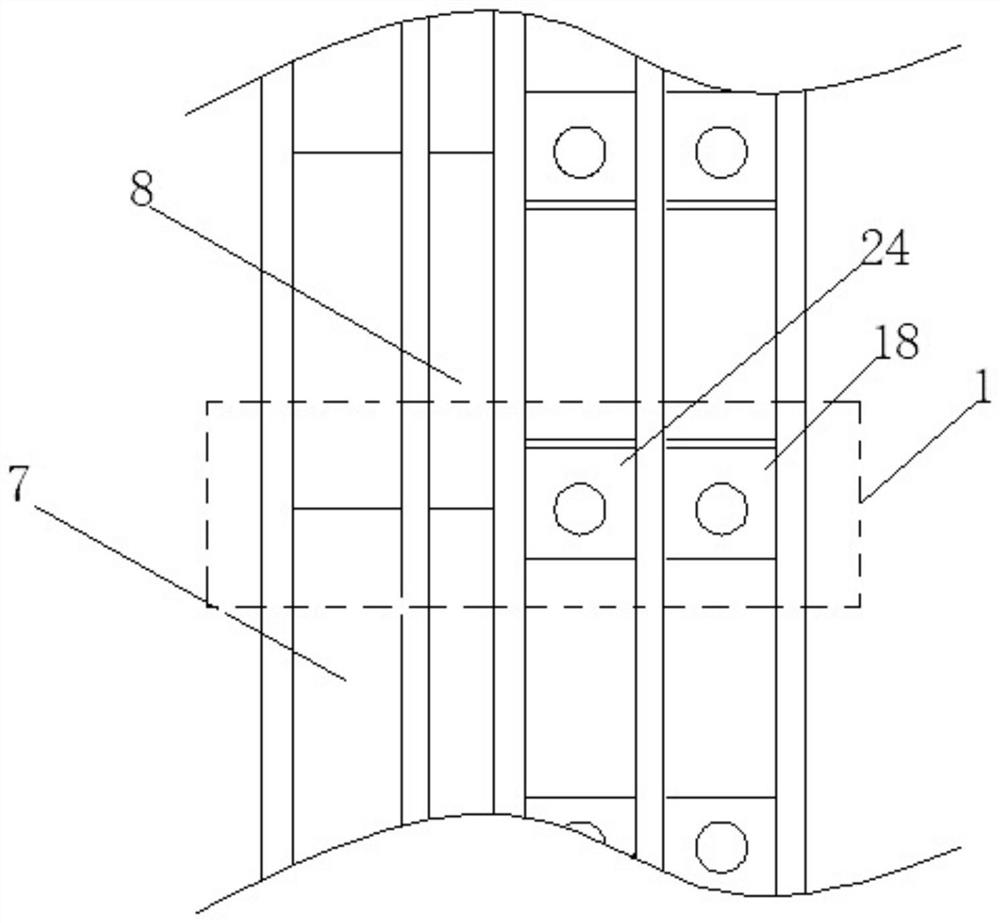
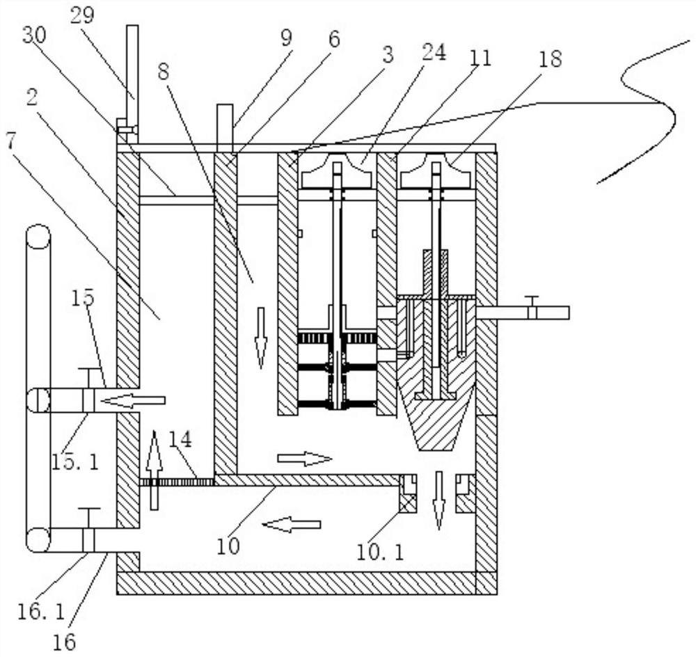
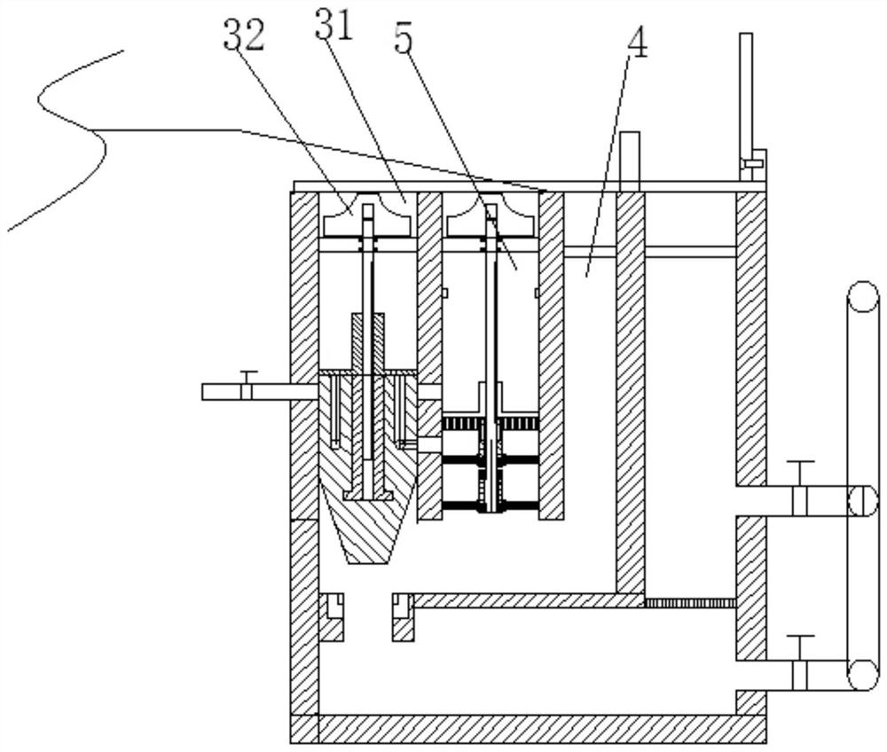
[0044] In the bridge drainage system, several drainage units 1 are respectively arranged on both sides of the bridge, and a drainage unit 1 is arranged at intervals on the same side of the bridge; 3 is divided into a first cavity 4 and a second cavity 5, the first cavity 4 is divided into a first drainage ditch 7 and a second drainage ditch 8 by a drainage side longitudinal partition plate 6, and the drainage side longitudinal partition plate 6. A longitudinal overflow plate 9 is installed on the upper part. The longitudinal overflow plate 9 at this position can control the rainwater to be discharged to the second drainage ditch 8 when the rainfall is small, and start the drainage mode of the small rainfall drainage stage. If necessary, a water pump can be set at a suitable position in the passage. The first drainage ditches 7 of all the drainage units on the same side of the bridge communicate with each other, and the second drainage ditches 8 of all the drainage units on the...

Embodiment 2

[0062] In the bridge drainage system, several drainage units 1 are respectively arranged on both sides of the bridge, and a drainage unit 1 is arranged at intervals on the same side of the bridge; 3 is divided into a first cavity 4 and a second cavity 5, the first cavity 4 is divided into a first drainage ditch 7 and a second drainage ditch 8 by a drainage side longitudinal partition plate 6, and the drainage side longitudinal partition plate 6. A longitudinal overflow plate 9 is installed on the upper part. The first drainage ditches 7 of all drainage units on the same side of the bridge are connected to each other, and the second drainage ditches 8 of all drainage units on the same side of the bridge are connected to each other.

[0063] The bottom of the longitudinal partition plate 6 on the drainage side is fixed with a transverse partition plate 10, and the transverse partition plate 10 extends from the longitudinal partition plate 6 on the drainage side to the side wall o...

Embodiment 3

[0080] In the bridge drainage system, several drainage units 1 are respectively arranged on both sides of the bridge, and a drainage unit 1 is arranged at intervals on the same side of the bridge; 3 is divided into a first cavity 4 and a second cavity 5, the first cavity 4 is divided into a first drainage ditch 7 and a second drainage ditch 8 by a drainage side longitudinal partition plate 6, and the drainage side longitudinal partition plate 6. A longitudinal overflow plate 9 is installed on the upper part. The first drainage ditches 7 of all drainage units on the same side of the bridge are connected to each other, and the second drainage ditches 8 of all drainage units on the same side of the bridge are connected to each other.

[0081] The bottom of the longitudinal partition plate 6 on the drainage side is fixed with a transverse partition plate 10, and the transverse partition plate 10 extends from the longitudinal partition plate 6 on the drainage side to the side wall o...


PUM


Abstract

The invention belongs to the technical field of bridge drainage devices, and particularly relates to a bridge drainage system and a drainage method thereof. A plurality of drainage units are arranged on the two sides of the bridge respectively, and the drainage units are arranged on the same side of the bridge at intervals; the drainage unit comprises a drainage ditch body, the upper portion of the drainage ditch body is divided into a first cavity and a second cavity by a longitudinal partition wall, the first cavity is divided into a first drainage ditch and a second drainage ditch by a drainage side longitudinal partition plate, and a longitudinal overflow plate is installed on the upper portion of the drainage side longitudinal partition plate. The first drainage ditches of all the drainage units on the same side of the bridge are communicated with one another, and the second drainage ditches of all the drainage units on the same side of the bridge are communicated with one another. The filter plate is arranged in the system, rainwater flow paths can be switched according to rainfall and ponding conditions on a bridge, and the rainwater can pass through the filter plate from top to bottom or from bottom to top in the drainage process, so that filtration and backwashing are realized, and blockage is avoided.

Description

technical field [0001] The invention belongs to the technical field of bridge drainage devices, and in particular relates to a bridge drainage system and a drainage method thereof. Background technique [0002] Public transportation in modern society mainly relies on bridges. In order to cope with rainy weather, drainage devices are often installed on both sides of bridges. Most of the existing drainage devices are simple floor drains with pipeline drainage. There may be the following problems. Make adjustments in the face of extreme weather such as heavy rain, and only filter through the floor drain. After a period of use, the drainage pipe is easy to block. Contents of the invention [0003] In view of the defects of the prior art, the present invention provides a bridge drainage system and a drainage method thereof, in which a filter plate is set inside the system, and the rainwater flow path can be switched according to the rainfall and the water accumulation on the br...

Claims


Application Information

Patent Timeline
Patent Type & Authority Applications(China)
IPC IPC(8): E01D19/08B01D29/03B01D29/56B01D29/66
CPCB01D29/03B01D29/56B01D29/66E01D19/086
Inventor 杨遂中杜勇王英帅尹建伟常天丽郭灿霞沈方李博李飞韩焱张志朱广俊李志敏毛亮门豪韩文雕程柯超张忆崔甲林胡刚领
Owner 郑州市公路工程公司
Learn More