
Spray pump rim thruster

A propeller and rim technology, which is applied in the field of energy conversion construction machinery, can solve the problems of speed increase and achieve the effects of increased power, low friction coefficient and good sealing performance

Inactive Publication Date: 2021-06-04
武汉波依迈科技有限公司
View PDF5 Cites 0 Cited by
  • Summary
  • Abstract
  • Description
  • Claims
  • Application Information

AI Technical Summary

Problems solved by technology

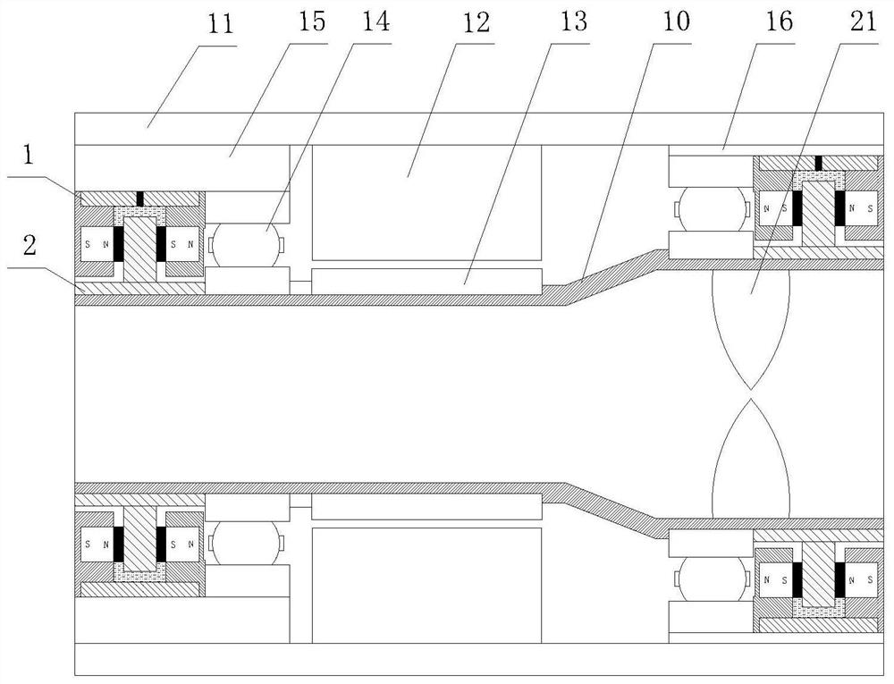
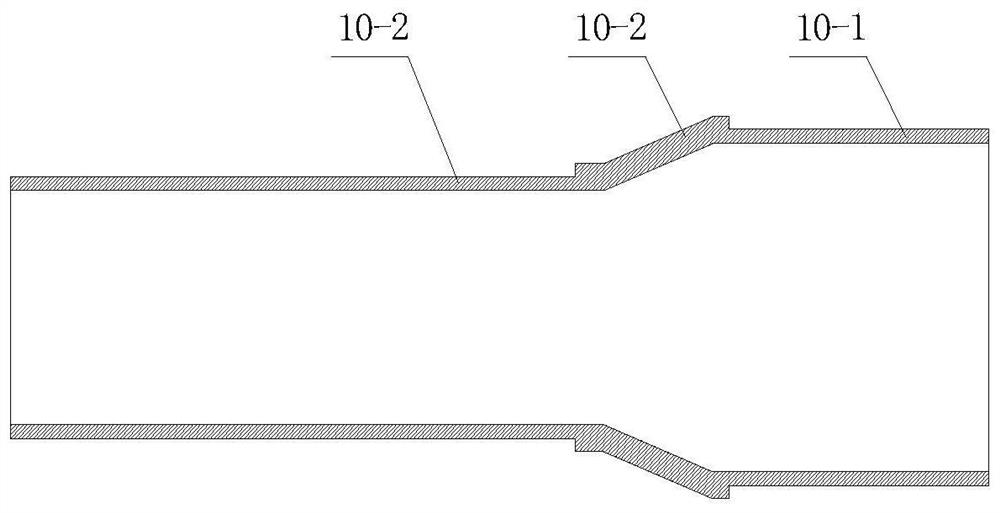
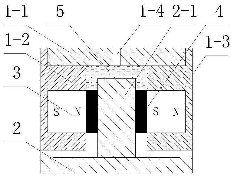
[0007] A jet pump rim propeller, including a rotating shaft, a casing, a stator and a rotor, the rotating shaft is hollow and trumpet-shaped, and is movably fixed in the end covers on both sides of the casing through bearings, and the rotating shaft includes The large end, the small end and the gradual change connecting the large end and the small end; the large end is used for fixedly installing the propeller, and the small end is used for fixedly installing the rotor; the stator is fixedly installed in the housing Corresponding to the rotor, a sealing assembly is provided on the side of the bearing; the sealing assembly includes an outer ring and an inner ring, which are respectively fixed on the end cover and the rotating shaft; the outer ring has a ring structure, and the inner ring There is a "U" or "V" groove, which is composed of an outer jacket and cover plates fixed on both sides of the outer jacket; the inner ring is provided with a salient pole, and the salient pole is placed in the groove, and the groove is connected to the inner ring. A "U" or "V" gap is formed between them, and the gaps on both sides are filled with magnetic fluid, and the magnetic fluid forms a magnetic fluid sealing band in the gaps on both sides due to the action of the magnetic poles; It is provided by a permanent magnet fixed on the outer ring or inner ring; the bottom gap closed by the magnetic fluid sealing strips on both sides is filled with a transition fluid with a density not less than that of the magnetic fluid; the transition fluid and the magnetic fluid are combined to form a "U" "Type or "V" type liquid sealing belt; its beneficial effect is that: the shaft is hollow and trumpet-shaped. During operation, the fluid enters from the large end and passes through the gradual change. The velocity changes due to the surge cross-sectional area At the narrowest point, the speed reaches the maximum value and the static pressure reaches the minimum value, so that the fluid is ejected at high speed from the small end, and the Venturi effect is used to increase the jet velocity of the water outlet and improve the propulsion efficiency, especially Combined with the trumpet-shaped structural characteristics of the rotating shaft, the small end after the gradual change greatly improves the installation space of the motor, and the motor part can be arranged at the small end. As we all know, the power of the motor has a great relationship with the volume of the motor. In the motor The larger the volume, the greater the power it can provide. The rim propeller breaks through the conventional design and has a reasonable layout, which perfectly solves the gap between the high-power stator and rotor and the limited installation space in the rim propeller. The contradiction of the rim propeller greatly improves its propulsion power and propulsion efficiency while ensuring the small size of the rim propeller; the bearing ensures the stability of the relative position of each part of the seal assembly during rotation, and provides a strong carrying capacity, and The structural forms of the inner ring and the outer ring jointly create a gap with a "U"-shaped cross section, and the magnetic fluid is filled in the gap on both sides; the magnetic poles on the side of the permanent magnet provide a magnetic field for the magnetic fluid at a close distance, The magnetic pole is the part with the strongest magnetic force in the permanent magnet, so that the magnetic fluid is gathered around the magnetic pole, forming a magnetic fluid sealing band in the gap on both sides, and filling the bottom gap closed by the magnetic fluid sealing band on both sides. The transition fluid whose density is not less than the magnetic fluid, generally the density of the magnetic fluid is 1.2×10 3 Kg / m 3 ~1.35×10 3 Kg / m 3 Among them, the transition fluid can choose saturated brine, glycerin and other liquids that are difficult to tolerate in the magnetic fluid; the transition fluid and the magnetic fluid are combined at the bottom of the groove to form a "U" or "V" type, continuous liquid seal; In the static sealing state, the magnetic fluid sealing belts on both sides play a sealing role and seal the transition fluid between the magnetic fluid sealing belts to form a liquid sealing belt together to realize the static pressure balance of the fluid in the U-shaped tube. When there is a pressure difference at both ends of the liquid sealing belt, the liquid sealing belt composed of magnetic fluid and transition fluid will shift to a new balance as a whole, the sealing surface will not be damaged, and the sealing effect will not be affected; in the dynamic sealing state, When the inner ring or outer ring in the rotating state drives the magnetic fluid and the transition fluid to rotate, the magnetic fluid and the transition fluid will generate centrifugal force at the same time. Since the density of the transition fluid is not less than that of the magnetic fluid, the transition fluid is always in the position of the magnetic fluid. At the bottom, according to the principle of static pressure balance of the fluid in the U-shaped tube, when the pressure difference between the two ends of the seal is zero, the liquid level difference between the two ends is zero. When the pressure difference is not zero, the liquid state composed of magnetic fluid and transition fluid The sealing belt will deviate as a whole in the gap to form a liquid level difference at both ends, so as to balance the pressure difference. The higher the speed, the greater the centrifugal force, and the extremely small liquid level difference can resist the strong external pressure difference. It can not only guarantee the excellent dynamic sealing effect, but also don’t have to worry about the problem of seal failure due to the influence of centrifugal force on the ferrofluid at high speed, which will cause the sealing thickness to become thinner and be broken down, especially when the speed is higher, the centrifugal force will be higher. Larger, the stronger the ability to resist the external pressure difference, suitable for the working condition that the external pressure difference increases with the increase of the speed, and the self-regulation ability is strong; according to the physical relationship between pressure, pressure and area, in order to further increase the influence of magnetic fluid on the magnetic force The lower the ability to resist the external pressure difference, the flow area at the "U"-shaped gap becomes smaller as it reaches the bottom; if the distance between the outer ring and the inner ring of the bearing is large enough, in order to simplify the structure, the sealing assembly can be directly integrated on the outer surface of the bearing. Between the ring and the inner ring, it is used as a sealed bearing

Method used


Image

  • Spray pump rim thruster
  • Spray pump rim thruster
  • Spray pump rim thruster

Examples


Embodiment 1

[0037] like Figure 1~4 As shown, a jet pump rim propeller includes a rotating shaft 10, a casing 11, a stator 12, and a rotor 13. The rotating shaft 10 is hollow and has a trumpet-like structure, and is movably connected to a shaft fixed to the casing 11 through a bearing 14. In the front end cover 15 and the rear end cover 16 on both sides, the rotating shaft 10 includes a large end portion 10-1, a small end portion 10-3 and a gradual change portion 10-2 connecting the large end portion and the small end portion; The inner side of the big end 10-1 is used for fixing the blade 21, and the small end 10-3 is used for fixing the rotor 13; the stator 12 is fixedly installed in the casing 11, corresponding to the rotor 13; The outer side of the bearing 14 is provided with a sealing assembly; the sealing assembly includes an outer ring 1 and an inner ring 2, which are respectively fixed on the end cover and the rotating shaft. ” type groove, which is composed of jacket 1-1, left c...

Embodiment 2

[0040] like Figure 5-6 As shown, a jet pump rim propeller includes a rotating shaft 10, a casing 11, a stator 12, and a rotor 13. The rotating shaft 10 is hollow and has a trumpet-like structure, and is movably connected to a shaft fixed to the casing 11 through a bearing 14. In the front end cover 15 and the rear end cover 16 on both sides, the rotating shaft 10 includes a large end portion 10-1, a small end portion 10-3 and a gradual change portion 10-2 connecting the large end portion and the small end portion; The inner side of the big end 10-1 is used for fixing the blade 21, and the small end 10-3 is used for fixing the rotor 13; the stator 12 is fixedly installed in the casing 11, corresponding to the rotor 13; The outer side of the bearing 14 is provided with a sealing assembly; the sealing assembly includes an outer ring 1 and an inner ring 2, which are respectively fixed on the end cover and the rotating shaft. ” type groove, which is composed of jacket 1-1, left c...

Embodiment 3

[0043] like Figure 7-8 As shown, a jet pump rim propeller includes a rotating shaft 10, a casing 11, a stator 12, and a rotor 13. The rotating shaft 10 is hollow and has a trumpet-like structure, and is movably connected to a shaft fixed to the casing 11 through a bearing 14. In the front end cover 15 and the rear end cover 16 on both sides, the rotating shaft 10 includes a large end portion 10-1, a small end portion 10-3 and a gradual change portion 10-2 connecting the large end portion and the small end portion; The inner side of the big end 10-1 is used for fixing the blade 21, and the small end 10-3 is used for fixing the rotor 13; the stator 12 is fixedly installed in the casing 11, corresponding to the rotor 13; The rotating shaft 10 has a hollow structure, with paddles 21 fixed on the inside; sealing assemblies are provided on both sides of the bearing 14; the sealing assembly includes an outer ring 1 and an inner ring 2, which are respectively fixed on the end cover a...


PUM


Abstract

The invention discloses a spray pump rim thruster which comprises a rotating shaft, a shell, a stator and a rotor, the rotating shaft is of a hollow and trumpet-shaped structure and is fixed in the shell through a bearing, a propeller is fixed to a large end, the rotor is fixed to a small end, and a sealing assembly is arranged on the side edge of the bearing; the sealing assembly comprises an outer ring and an inner ring which are respectively fixed on an end cover and the rotating shaft; the outer ring is of an annular structure, and a groove is formed in the inner side; salient poles are arranged on the inner ring, the salient poles are arranged in the groove, U-shaped gaps are formed between the salient poles and the groove, the gaps in the two sides are filled with magnetofluid, and magnetofluid sealing belts are formed in the gaps in the two sides through the magnetofluid under the action of the magnetic poles; transition fluid with the density not smaller than that of the magnetic fluid is packed in a bottom gap sealed by the magnetofluid sealing belts on the two sides; and the transition fluid and the magnetic fluid are combined together to form a U-shaped liquid sealing belt. The invention provides the high-performance high-power spray pump rim thruster which is good in sealing performance and low in friction coefficient by utilizing magnetofluid sealing.

Description

technical field [0001] The invention belongs to the field of energy conversion engineering machinery, in particular to a jet pump wheel rim propeller with good sealing performance and low friction coefficient. [0002] technical background [0003] In recent years, with the development of offshore engineering and water entertainment, the performance requirements of propellers have become higher and higher. Traditional shaft-driven propellers have many components, complex structures, large cabins, and large energy losses. Vibration and noise Disadvantages such as difficult control, high construction and maintenance costs have gradually become prominent, and they can no longer meet the work requirements better, leading people to gradually turn their attention to more advanced shaftless propulsion systems. [0004] Shaftless drive propellers are divided into two types: hubless and hub. The propeller mainly includes a stator and a rotor with a motor. The rotor is cylindrical. The...

Claims


Application Information

Patent Timeline
Patent Type & Authority Applications(China)
IPC IPC(8): B63H11/04F16J15/43
CPCB63H11/04F16J15/43
Inventor 王前进
Owner 武汉波依迈科技有限公司
Learn More